Download
1 / 16
170 likes | 296 Views
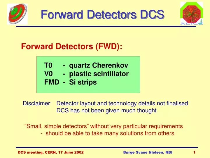
Forward Detectors DCS. Forward Detectors (FWD): T0 - quartz Cherenkov V0 - plastic scintillator FMD - Si strips. Disclaimer: Detector layout and technology details not finalised DCS has not been given much thought.

E N D
Forward Detectors DCS Forward Detectors (FWD): T0 - quartz Cherenkov V0 - plastic scintillator FMD - Si strips Disclaimer: Detector layout and technology details not finalised DCS has not been given much thought ”Small, simple detectors” without very particular requirements - should be able to take many solutions from others Børge Svane Nielsen, NBI
Forward detectors in ALICE Si-1 V0-R Si-2 T0-R Si-3 Børge Svane Nielsen, NBI
T0 detector • Precise event timing (=50ps) • Start detector for ALICE-TOF • Main LVL0 event trigger • Pre-trigger for TRD • Rough on-line vertex determination <1.5 cm • Beam-gas suppression • Output Signals: • T0 = (tr+tl)/2+td • T0v = tr-tl • T0-L, T0-R • Time and energies • 3 levels of sum energy (low, medium, high) Børge Svane Nielsen, NBI
T0 controls • High voltage: • PM tubes: 1500-2000 V • 1 supply per counter 24 channels total • Electronics: • 48 discriminator channels • 24 ADC + 27 TDC channels • parameter loading & monitoring ? • Calibration • laser: parameters & controls? • Trigger circuitry: • parameters & monitoring ? Børge Svane Nielsen, NBI
V0 detector • Two segmented scintillator hodoscopes on either side of IP • Minimum bias trigger: p-p and Pb-Pb • Main on-line LVL0 centrality trigger: Pb-Pb • Background filter for the dimuon spectrometer • Two arm for beam-gas rejection • Luminosity control • Multiplicity measurement (high occupancy) Absorber V0-R Børge Svane Nielsen, NBI
V0 layout • V0-L and V0-R: 5 rings each • Rings 1-4: 30° sectors (12) • Ring 5: 15° sectors (24) • Plastic scintillator • Wave-length shifting fibers in groove • Clear optical fibers for light transport (25 m) • Photomultiplier Børge Svane Nielsen, NBI
V0 controls • High voltage: • PM tubes: 1500-2000 V • 1 supply per counter 144 channels total • Back-end electronics: • parameters & controls ? • Trigger circuitry: • parameters & monitoring ? Børge Svane Nielsen, NBI
FMD detector Si1 Si3 Si2 Børge Svane Nielsen, NBI
FMD ring layout Full FMD = 3 inner rings + 2 outer rings Inner: Rin=4.2 cm Rout=17.2 cm Outer: Rin=15.4 cm Rout=28.4 cm 128 256 20x2x128=5120 10x2x256=5120 Børge Svane Nielsen, NBI
FMD ring assembly Si FEE Hybrid Support Honeycomb Børge Svane Nielsen, NBI
FMD Si sensor VA-32 pre-amp. chip 256 strips 2 sectors Connector Daisy chain 256 ch => 25 sec DT Børge Svane Nielsen, NBI
Cable function Segments (wafers) # lines Phi sectors Cable type Radial strips Hybrids # cables for inner ring Chips/ Hybrid # cables for outer ring FE Chips FE Channels FE controls 10 Shielded twisted pair 2 2 Si 1 inner 10 20 256 10 16 160 5,120 Analog data out 1 Shielded twisted pair 20 20 Si 1 outer 20 40 128 20 8 160 5,120 FE power 4 Shielded twisted pair 20 (or 10?) 20 Si 2 inner 10 20 256 10 16 160 5,120 Bias voltage 1 Shielded twisted pair ?? 10 20 Si 2 outer 20 40 128 20 8 160 5,120 Si 3 inner 10 20 256 10 16 160 5,120 Total system 70 140 70 720 25,600 FMD channels and cables FMD channel count: FMD cable count: Børge Svane Nielsen, NBI
FMD controls • High voltage: • bias voltages for Si strips: 50-100 V • minimum 1 supply per half ring 10 channels total • maximum 1 supply per segment 70 channels total • Low voltage: • power for front end electronics: 5 V ? • 1 supply per segment 70 channels total • Front end electronics: • design still very uncertain, only preamp type chosen • options: analog or digital read-out • monitor a few temperatures • down-loading of parameters • Back end electronics: ??? Børge Svane Nielsen, NBI
TPC laser DCS Details: http://www.nbi.dk/~borge/tpclaser Børge Svane Nielsen, NBI
TPC laser UV Laser: power supply and cooling supplied by Spectron Lasers. Controlled by RS232 to simple DOS program - reprogramming desirable. Børge Svane Nielsen, NBI
TPC laser controls • High voltage and cooling of laser: • HV and flash pulse circuit • cooling water circulation unit • control interface to RS232 Rack unit supplied by Spectron Lasers company • Movable optics controls: • picomotor drives (a la stepping motors) • 10-20 individual motors • Cameras: • CCD cameras for beam position monitoring • 8-10 cameras Børge Svane Nielsen, NBI