Download
1 / 17
170 likes | 303 Views
20b. Gaseous Energy Absorber, 21a. High Pressure RF Cavities. New Money for New Approaches DOE Small Business Innovation Research (SBIR) Grant Proposals (phase I $100k, phase II $750k) by MUONS INC. Ankenbrandt, Black, Cassel, Johnson, Kaplan, Kuchnir, Moretti, Popovic.

E N D
20b. Gaseous Energy Absorber,21a. High Pressure RF Cavities New Money for New Approaches DOE Small Business Innovation Research (SBIR) Grant Proposals (phase I $100k, phase II $750k) by MUONS INC. Ankenbrandt, Black, Cassel, Johnson, Kaplan, Kuchnir, Moretti, Popovic MUCOOL/MICE
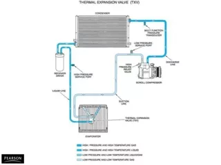
SBIR 21b. Gaseous Energy Absorber Conceptual Design • Continuous GH2 (or He) • Eliminate LH2 and flasks • Double Flip channel • constant low b • Gas density gives dE/dx for dV/dz • T and P to be optimized • Paschen’s Law suppresses RF Breakdown • Gas fills RF cavities MUCOOL/MICE
Present Double Flip Section MUCOOL/MICE
Minimum of Paschen Curve MUCOOL/MICE
High Pressure Paschen Curve MUCOOL/MICE
20b. Project Goal • Unlike schemes now under consideration, which are based on using many large flasks of liquid hydrogen energy-absorber, the novel idea of using a gas absorber leads to a conceptually simpler design with better cooling and several engineering advantages. This proposal is to develop the design of an ionization-cooling channel based on a gaseous absorber and to produce a channel section suitable for testing in a muon beam (MICE). MUCOOL/MICE
Some Engineering Advantages of GH2 Energy Absorber • Eliminates LH2 containers • Better cooling, fewer losses, shorter channel • Adds operational flexibility • Vary dE/ds for changes in RF • Cools Be RF windows • Aids detector problems • eliminates dark currents • Well-suited for low-temp RF operation MUCOOL/MICE
20b. Phase I Goal • The primary goal of Phase I is to produce a conceptual design of a muon ionization-cooling channel with gaseous absorber which has been optimized by computer simulations to be superior to those based on liquid absorbers. • ~6 months, $100k MUCOOL/MICE
Second Proposal Pushes the Envelope of RF Gradient • Breakdown voltage Vb~gas density3/2 • Accelerating Voltage ~dE/dx ~ gas density • Vb/VRF ~ gas density1/2 • things only get better as density increases • at 300K, 10 MV/m, 84 atm H2 gives dE/dx • but 44 atm will hold off 50 MV/m MUCOOL/MICE
And the Envelope of Low Temperature RF • Cu ResistivityT (K ) (10^(-8) Ohm-m) Ratio1 0.002 862.50 1 0 0.00202 853.96 2 0 0.0028 616.07 3 0 ~0.017 ~2404 0 0.0239 72.18 6 0 0.0971 17.77 8 0 0.215 8.021 0 0 0.348 4.96 1 5 0 0.699 2.47 2 0 0 1.046 1.65 2 7 3 1.543 1.12 3 0 0 1.725 1.004 0 0 2.402 0.72 MUCOOL/MICE
Surface Resistance • Rs, the relevant quantity for power and voltage considerations, is the resistivity, , divided by the skin depth, s = (f)1/2. Thus Rs = (f )1/2. • Two complications to this relationship are the • effects of an external magnetic field • expected to be less than 10% • somewhat dependent on the placement of the coils • anomalous skin depth • small at our proposed temperatures and frequencies MUCOOL/MICE
21a Project Goal Unlike any previous particle accelerator, muon beams in an ionization cooling channel are not only allowed but are required to be accelerated through an energy absorbing material. This proposal is to develop very high voltage RF cavities by filling them with cold, pressurized helium or hydrogen gas, which also acts as the energy absorber, to suppress high-voltage breakdown. MUCOOL/MICE
21a Phase I Goal The primary goal of Phase I is to build an RF test cell suitable for testing the breakdown characteristics of gases to be used in ionization cooling applications. The test cell will allow the exploration of Paschen’s Law, relating breakdown voltages to gas density, over a range of temperatures, pressures, external magnetic fields, and ionizing particle radiation. MUCOOL/MICE
Phase I RF test cell MUCOOL/MICE
High-P RF Coupling Loop MUCOOL/MICE
How Low Can You Go? • At very low temperature in the extreme anomalous conduction region, where the mean free path of the conduction electrons become very large compared with the skin depth, the surface resistance of the conductor becomes independent of the d.c. conductivity and scales as frequency to the 2/3 power. At 80K, copper is not anomalous at 805 MHz or 200 MHz, so improvement factors of about 3 in surface resistance are to be expected. • In the extreme anomalous region, a factor 6 improvement of the surface resistance of copper at 1.2 GHz at 30K. Using the above scaling we could expect an improvement factor of about 8 at 805 MHz and 20 at 200 MHz. MUCOOL/MICE
A Vision of Perfect Success • 40 MV/m • Channel <1/4 length of previous designs • Choices: Power vs Gradient, dE/ds vs B.A. • Simple Design • One BIG Gaseous Absorber, integrated into • RF cavities all operating at 30K, with only • Two beam windows • Present LH2 team expertise makes it all happen (safety, RF, windows, cryo, sims,…. MUCOOL/MICE