Download
1 / 123
1.23k likes | 1.26k Views
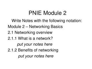
vSphere 4.0 Module 4 – Networking. Emiliano Turra Product Support Engineering. VMware Confidential. Rev. G. Agenda. Module 0 - Product Overview Module 1 - VI Installation-Upgrade Module 2 - VirtualCenter Module 3 - Storage Module 4 - Networking. Agenda – Lessons for Module 4.

E N D
vSphere 4.0Module 4 – Networking Emiliano Turra Product Support Engineering VMware Confidential Rev. G
Agenda • Module 0 - Product Overview • Module 1 - VI Installation-Upgrade • Module 2 - VirtualCenter • Module 3 - Storage • Module 4 - Networking vSphere 4- Mod 4 - Slide
Agenda – Lessons for Module 4 • Module 4 - Networking • Lesson 1: vNetwork Distributed Switch • Lesson 2: Private VLAN • Lesson 3: IPv6 • Lesson 4: VMXNET Generation 3 • Lesson 5: VMDirectPath I/O • Lesson 6: Virtual Machine Communication Interface (VMCI) • Lesson 7: Basic Troubleshooting Tips vSphere 4- Mod 4 - Slide
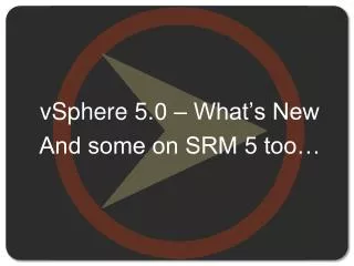
vNetwork Distributed Switch Standard Switch Distributed Switch vCenter vCenter vSphere 4- Mod 4 - Slide
Distributed Switch Terminology • Terminology (in Red the official names) • DVN - vNetwork • Distributed Virtual Network, is the umbrella name under which the new network infrastructure components are grouped. The official name that customers will hear is vNetwork • dvSwitch, DVS or Distributed Virtual Switch - vNetwork Distributed Switch • Abstraction of multiple hosts sharing the same configuration for vSwitches and portgroups. • vSwitch - vNetwork Standard Switch • The “standard” virtual switch that is available in ESX 3.x and 4.x without vNetwork • dvPort • Port in a dvSwitch that allows VMs, vnics, VMKernel or Service Console nics. • dvPort status is stored in VC Database, so it is persistent across hosts • dvPortgroup • Collection of DVPorts that share the same configuration. vSphere 4- Mod 4 - Slide
Distributed Switch • Distributed Switch: this means that the configuration is centralised to vCenter. • All the hosts that belong to a dvSwitch will not need further configuration to be compliant • Distributed Switch: the behaviour will still be the same (or consistent) with the vSwitch we are used to deal with: • dvPortgroups, as a set of dvPorts (the dv equivalent of Portgroups as a set of ports in a vSwitch) • Configuration is inherited from dvSwitch to dvPortgroup (the equivalent of what happens for vSwitch/Portgroup) • VMs, Service Console interface (vswif) and VMKernel interfaces can be connected to dvPortgroups as they could be connected to Portgroups in vSwitches • Hosts still own 2 configuration contexts, which are therefore not administered centrally via vNetwork: • Service Console and VMKernel interfaces • Physical NICs and their assignment to dvSwitch Uplink groups vSphere 4- Mod 4 - Slide
Data Plane Distributed Virtual Switch Architecture • Control Plane (CP) and Data Plane, or I/O Plane are separated. • CP, responsible for configuring dvSwitches,dvPortgroups, dvPorts, Uplinks, NICTeaming and so on, and for coordinating the migration of the ports, runs on vCenter • DP, responsible for performing the forwarding, runs inside the VMKernel of the ESX (Default VMware implementation of CP is via hidden vSwitch). vCenter Distributed vSwitch Control Plane ESX 4 ESX 4 ESX 4 Distributed vSwitch vSwitch vSwitch vSwitch vSwitch vSphere 4- Mod 4 - Slide
Data Plane Distributed Virtual Switch Architecture – Data Plane • Filters (DVN Switch API, or dvFilter) • Forwarding (DVN Appliance API, or VSafe-net) IO Filter IO Filter IO Filter vSwitch Port Port Port Forwarding Engine Teaming Engine Port Port IO Filter IO Filter vSphere 4- Mod 4 - Slide
Uplink Abstraction UPLINK groups allow for abstraction from the physical implementation of each server. • Each Physical host can contribute with up to 1 NIC to each Uplink group • vCenter will only see the uplink groups when configuring the Distributed Switch, because each host can contribute in a different way (vmnic0,1,2,3,…) vmnic0,1,2,3,…? vCenter vSphere 4- Mod 4 - Slide
Comparing Standard and Distributed Switch • Both • can forward L2 frames • can segment traffic into VLANs • can use and understand 802.1q VLAN encapsulation • can have more than one uplink (Nic Teaming) • can have traffic shaping for the outbound (TX) traffic • Only Distributed Switch • can shape inbound (RX) traffic • has a central unified management interface through VC • supports Private VLANs (PVLANs) • provides potential customisation of Data and Control Planes vSphere 4- Mod 4 - Slide
Distributed Switch does/does not’s • DS is/does • Simplify datacentre setup by centralising network configuration • Will make it easier for VI Admins to add hosts to the cluster and have them immediately VMotion compatible • Each dvPort is unique across the dvSwitch, and therefore across the cluster, and will follow the “client” if it is moved around, for example VMotion of a VM. • DS is NOT: • A single and whole Standard Switch across hosts, because: • It behaves roughly as if you had Standard Switches configured consistently across the hosts • The traffic between two VMs on the same dvPortgroup but on different hosts will still go through the physical network via the Distributed Switch Uplinks • PVLANs require physical configuration or VMotion will break connectivity. vSphere 4- Mod 4 - Slide
Standard Switch + Host Profiles = DS ? • Standard Switch + Host Profiles = Distributed Switch ? • You get all the Standard Switch Features plus the ability to re-create them on new hosts • No DS features • Manual process of applying new modifications to all the hosts • There is no Uplink group, so when vmnic names differ across hosts, configuring nicteaming might be impossible via one single profile • Changes are applied in maintenance mode vSphere 4- Mod 4 - Slide
Custom Distributed Switch • I/O Plane (Data Plane) and Control Plane can be replaced with 3rd party versions • Custom Data Plane implements Forwarding/Filtering/Teaming, basically replacing the vSwitch • Custom Control Plane is implemented as an appliance, and will be responsible for handling the configuration of the ports (storing, changing and migrating), and coordinating the configuration across DPs (across hosts) • Data Plane Agents (DPAs) will run as VMKernel Worlds and will be responsible of communication between CP and DPs vSphere Client Plugin vC Extension vCenter Control Plane Control Plane Appliance ESX 4 ESX 4 ESX 4 Distributed vSwitch DataPlane Agent Data Plane vSwitch vSwitch vSphere 4- Mod 4 - Slide
Creating Distributed Virtual Switch - 1 • Go to Home > Inventory > Networking • If you are in other locations, the “New DVS” button is disabled • Create a new Distributed Switch • Specify: • Name of the Distributed Switch • Number of Uplink Ports • Uplinks can be renamed/added afterwards vSphere 4- Mod 4 - Slide
Creating Distributed Virtual Switch - 2 • Add hosts and Uplinks (vmnic groups) from Cluster • An Uplink is to a Distributed Switch what a vmnic is to a Standard Switch • Due to the fact that the Distributed Switch is a “logical/abstract” entity that exists across hosts, the association between a Distributed Switch and each host’s vmnic is done via this further abstraction called Uplink. • What is called Uplink here is a group of vmnics, grouped by the VI Administrator when adding hosts/vmnics to the Distributed Switch vSphere 4- Mod 4 - Slide
Creating Distributed Virtual Switch – 3 • Select whether to create a default Portgroup or not • The Distributed Switch is ready Uplinks vSphere 4- Mod 4 - Slide
Assigning Uplinks to a Distributed Switch • Uplinks are associated automatically at Distributed Switch creation time • If changes need to be applied, they have to be applied from the host • Therefore in vCenter, go to Host > Configuration > Networking • Select DVS view • Click on “Manage Physical Adapters” • If you click on the first “<Click to Add NIC>”, the NIC will be added to the “Pending Uplink Assignment” group and assigned automatically when you press “Ok” • Click on “<Click to Add NIC>” below the Uplink group you wish to assign the vmnic to vSphere 4- Mod 4 - Slide
Managing Distributed Switch Distributed Switch properties are grouped in 3 tabs: • Properties • General • Advanced • Network Adapters • View Physical adapter contributed by each member (ESX). No modification allowed from this screen, you need to go to the specific host configuration for managing Uplinks • Private VLAN • Where you can associate/edit Primary and Secondary PVLANs. • Changes might not take place if you try to edit PVLANs that are in use, disconnect the VMs first. We will see PVLANs later vSphere 4- Mod 4 - Slide
Managing Distributed Switch - General • General • Allows you to define (Prompted also at DVS Creation time) • the DVS name, • the number of UPLINK ports, • Additionally, allows you to define • notes • It allows also to edit the Uplink names. vSphere 4- Mod 4 - Slide
Managing Distributed Switch - Advanced • Advanced • Allows to define: • Max value for Maximum Transmission Unit (Useful for enabling Jumbo Frame) For the Standard vSwitch, the only options are: esxcfg-vswitch –m and -l • Cisco Discovery Protocol Status For the Standard vSwitch, the only options are: esxcfg-vswitch –B and -b • Administrator’s details vSphere 4- Mod 4 - Slide
Distributed Switch Portgroups • Similarly to what happens with the standard vSwitch, also in a Distributed Switch Portgroup: • represents a group of Ports that share the same configuration template. • does not constitute the means to segregate traffic • Settings divided into 3 categories : • General • Policies • Security • Traffic Shaping • VLAN • Teaming and Failover • Miscellaneous • Advanced vSphere 4- Mod 4 - Slide
Distributed Switch Portgroups - General • General • Allows you to define • The name of the portgroup • A description • The number of ports available • The type of Port Binding, which can be • Static • Dynamic • None (Ephemeral ports) vSphere 4- Mod 4 - Slide
Port Binding • Static Binding (Default): means that the dvPort will be assigned to the VM at configuration time. Once all the ports are “booked” by VMs, it will not be possible to connect any more VM, independently from the fact that the connected VMs are powered up or not, and an error message will be displayed • Dynamic Binding: means that the dvPort will be assigned at the moment of powering the VM up. This option allows for over committing the number of dvPorts. • Ephemeral Ports or No Binding: this behaviour has been introduced to resemble the behaviour in the standard vSwitch. If you select this option, the number of ports will be automatically set to 0, and the Portgroup will allocate one port for each connected VM, up to the maximum number of ports available in the Switch. vSphere 4- Mod 4 - Slide
Distributed Switch Portgroups – Security • Policies (shows all the options below together) • Security • Similar to what we have already seen in the vSwitch, this section allows you to define security policies for: • Promiscuous mode • Allowing machines to see the traffic of all the other machines in the DVS • Mac address changes • Allows VMs to receive frames with a Mac Address that is different from the one configured in the VMX • Forged Transmits • Allows VMs to send frames with a Mac Address that is different from the one specified in the VMX vSphere 4- Mod 4 - Slide
Distributed Switch Portgroups – Traffic Shaping - 1 • Policies (shows all the options below together) • Traffic Shaping • Allows you to define ingress and egress traffic shaping. • Ingress shaping is a new feature, and available only with DVS (not on vSwitch) vSphere 4- Mod 4 - Slide
Distributed Switch Portgroups – Traffic Shaping – 2 • Traffic Shaping concepts: • Average Bandwidth • Target traffic rate cap that the switch will try to enforce. Every time a client uses less than the defined Average Bandwidth builds up credit. • Peak Bandwidth • Extra bandwidth available, above the Average Bandwidth specified above, for a short burst. The availability of the burst depends on credit accumulated so far • Burst Size • Amount of traffic that can be transmitted or received at Peak speed (Combining Peak Bandwidth and Burst Size you can calculate the maximum allowed time for the burst) vSphere 4- Mod 4 - Slide
Distributed Switch Portgroups – VLAN - None • Policies(shows all the options below together) • VLAN (Allows you to specify the VLAN behaviour of the dvSwitch, VDS Only): • NONE • Physical equivalent to: No VLAN Tagging • Standard vSwitch equivalent to: VLAN ID option set to 0 • EST – External Switch Tagging vSphere 4- Mod 4 - Slide
Distributed Switch Portgroups – VLAN – Single VLAN • Policies(shows all the options below together) • VLAN (Allows you to specify the VLAN behaviour of the dvSwitch, DVS Only): • VLAN • Physical equivalent to: VLAN in Access/Untagged mode • Standard vSwitch equivalent to: VLAN ID option • VLAN ID 4095 is not allowed here • VST – Virtual Switch Tagging vSphere 4- Mod 4 - Slide
Distributed Switch Portgroups – VLAN - Trunk • Policies(shows all the options below together) • VLAN (Allows you to specify the VLAN behaviour of the dvSwitch, VDS Only): • VLAN Trunking • Physical equivalent to: VLAN in Trunk/Tagged mode • Standard vSwitch equivalent to:VLAN ID set to 4095 • VGT – VLAN Guest Tagging • VDS Only: option to specify the range of VLANs to trunk, to improve security. vSphere 4- Mod 4 - Slide
Distributed Switch Portgroups – VLAN - PVLAN • Policies(shows all the options below together) • VLAN (Allows you to specify the VLAN behaviour of the dvSwitch, DVS Only): • PVLAN • Physical equivalent to: PVLAN • Standard vSwitch equivalent to:Does not exist • PVLAN • option to specify which Primary and Secondary VLAN to use (Selecting from the list defined in the Switch) vSphere 4- Mod 4 - Slide
Distributed Switch Portgroups – Teaming & Failover • Policies(shows all the options below together) • Teaming and Failover • Allows policies to be defined for: • Load Balancing • Failover detection • Notify Switches • Failback • Failover order • Specific Uplink usage From the screenshot on the right, you can see how the Active/Standby status is applied to each uplink group (dvUplink1 and 2 in this case), and not to the vmnics directly, as it used to be with standard vSwitches vSphere 4- Mod 4 - Slide
Distributed Switch Portgroups – Misc. • Policies(shows all the options below together) • Miscellaneous • Allows you to block all the dvPorts of the dvPortgroup, DVS Only vSphere 4- Mod 4 - Slide
Distributed Switch Portgroups – Advanced - 1 • The dvPortgroup Advanced subcategory is different from dvSwitch: • It allow each single dvPort to override the settings of the dvPortgroup. clicking on “Edit Override Setting” the VI Admin can also specify which properties to allow/not allow to be overridden at lower levels. vSphere 4- Mod 4 - Slide
Distributed Switch Portgroups – Advanced - 2 • The dvPortgroup Advanced subcategory is different from dvSwitch: • It allow each single dvPort to override the settings of the dvPortgroup. clicking on “Edit Override Setting” the VI Admin can also specify which properties to allow/not allow to be overridden at lower levels. vSphere 4- Mod 4 - Slide
Configuring Distributed Switch Virtual Adapters -1 • Two types of Virtual Adapters: • Service console vswif • VMKernel vmknic • To use Virtual Adapters inside a dvSwitch, you need to configure them via Host > Configuration > Networking, as this is not a cluster-wide option. • Select Distributed Virtual Switch view and click on “Manage Virtual Adapters” vSphere 4- Mod 4 - Slide
Configuring Distributed Switch Virtual Adapters -2 • You’ll be prompted with the “Manage Virtual Adapters” dialog, where you can: • Add a new adapter • If you already have DVS virtual Adapters, you’ll be able to: • Edit the adapter (IP address/netmask, default gateway, DNS servers) • Migrate it back to a vSwitch • Delete it (Deleting the last vswif is not allowed) vSphere 4- Mod 4 - Slide
Configuring Distributed Switch Virtual Adapters -3 • If you click on “Add”, for each Virtual Adapter type, there will be 2 options: • Create a new Adapter • Migrate the existing from vSwitch to dvSwitch • Either way, you’ll be prompted to specify an existing dvPortgroup to be connected to vSphere 4- Mod 4 - Slide
Migrating from Standard Switches • If after selecting “Add”, you chose to “Migrate existing virtual network adapters”, you’ll be prompted with the form below • Select which adapters you wish to migrate • For each selected adapter, specify which dvPortgroup you want to connect it to. • The migration will take care of not interrupting the traffic, so for example vCenter won’t show the ESX as disconnected even if you migrate its only vswif interface vSphere 4- Mod 4 - Slide
Migrating from vSwitches - logs Example: migrating vswif2 with IP address 192.168.9.1 (Hex 0x109a8c0) from vSwitch0 to dvSwitch: cpu1:4175)DVSDev: DVSDevDataSet: setting data com.vmware.common.port.connectid on port 97 cpu3:4177)DVSDev: DVSDevDataSet: setting data com.vmware.common.port.portgroupid on port 97 cpu4:4179)DVSDev: DVSDevDataSet: setting data com.vmware.common.port.block on port 97 cpu4:4170)DVSDev: DVSDevDataSet: clearing data com.vmware.common.port.shaper.input on port 97 cpu4:4168)DVSDev: DVSDevDataSet: clearing data com.vmware.common.port.shaper.output on port 97 cpu1:4167)DVSDev: DVSDevDataSet: setting data com.vmware.etherswitch.port.teaming on port 97 cpu3:4178)DVSDev: DVSDevDataSet: setting data com.vmware.etherswitch.port.security on port 97 cpu3:4169)DVSDev: DVSDevDataSet: setting data com.vmware.etherswitch.port.vlan on port 97 cpu1:4175)DVSDev: DVSDevDataSet: clearing data com.vmware.etherswitch.port.ipfix on port 97 cpu3:4177)DVSDev: DVSDevDataSet: setting data com.vmware.common.port.statistics on port 97 cpu0:4096)Tcpip_Socket: vmk_set_ip_address:968: index = 145660792, ip_addr = 0x109a8c0, netmask = 0xffffff cpu1:4109)Mirror: Mirror_PortDisable: removing wildcard INPUT match port vswif2(0x8) from session legacy_promiscuous cpu0:4096)Net: NetDisconnect:1250: disconnected from net vSwitch0, PortID = 0x8 Preparing dvPort 97 to receive vswif2 vSphere 4- Mod 4 - Slide
Migrating from vSwitches - logs cpu0:4096)NetDVS: DVS_PortAssociate:413: Connecting to DVS 49 89 34 50 eb b6 a0 ae-d9 d3 3e e1 68 b4 5d 45 port 97 cpu0:4096)NetDVS: DVSPortAssociate:1155: port 0x410004256ce0 (type 1) cpu0:4096)NetDVS: DVS_PortAssociate:438: Connected to DVS port 97 (type 1), dvs 49 89 34 50 eb b6 a0 ae-d9 d3 3e e1 68 b4 5d 45 cpu0:4096)NetPortset: Portset_ConnectPort:1251: newID 0x300000c, newIDIdx 0xc, psMask 0x1ff, newPort 0x41000412db80, portsInUse 6, portCfgName <none> cpu0:4096)Net: NetConnectCommon:1054: connected to net (null), portset 0x410004004428, PortID = 0x300000c, status 0x0 cpu6:4111)Net: COSVMKDev_Enable:1419: port = 0x300000c, cosStateVA = 0x41007cb88000, cosStateVP = 0x41007cb88000, cosStateLen=0x649c cpu6:4111)Net: COSVMKDev_Enable:1444: txRing = 0x41007cb8949c, rxRing = 0x41007cb8809c, numRxBufs = 0x80, numTxBufs = 0x80 cpu6:4111)Net: COSVMKDev_Enable:1468: COS VMK gen count = 11 cpu6:4111)Net: COSVMKDev_Enable:1481: Enabling NIC in the shadow vmkernel tcpip stack cpu6:4111)Tcpip_Interface: vmk_nic_attach:893: ether attach complete cpu6:4111)NetDVS: DVS_PortLinkUp:501: DVS_PortLinkUp portID 0x300000c DVS port 97 cpu6:4111)NetPort: PortBlockSet:2040: resuming traffic on DV port 97 cpu6:4111)VLAN: VLAN_UpdateDVSPortCfg: VLAN 64 configured for DVPort 50331660 cpu6:4111)etherswitch: NCP_AddBeaconVID: 64 cpu6:4111)Mirror: MirrorSessionWildcardAddPort: adding wildcard match port vswif2(0x300000c) for INPUT to session legacy_promiscuous vSphere 4- Mod 4 - Slide
Migrating VMs Between dvPortgroups • VI4 introduces a new feature that allows you to mass-move VMs from one dvPortgroup to another • To initiate a Migration, go to the Summary page of the dvSwitch (from Host > Inventory > Networking) • Click on “Migrate Virtual Machine Networking” • Select Source and Destination dvPortgroup • Click on “Show Virtual Machines” • Select the VMs you want to Migrate vSphere 4- Mod 4 - Slide
vm1 vm2 vm2 vm2 vm2 vm2 Migrating to DS Step by Step • Steps: • Create a DS with as many Uplink groups as Physical NICs connected to the Standard Switches • Create in the DS as many Portgroups as you already have in the SS • Assign Uplinks to each Portgroup in the DS • Break each teaming and transfer one NIC from each vSwitch to a corresponding Uplink group • Migrate the Virtual Adapters and the Virtual Machines to the appropriate Portgroups • Transfer the remaining uplinks to the Uplink groups associated with the appropriate Portgroups • Remove the Standard Switches and their Portgroups vSwitch0 DS vswif0 0 Uplink1 Uplink1 dvPG0 1 vmk0 Uplink2 Uplink2 Uplink3 Uplink3 vSwitch1 dvPG1 2 Uplink4 Uplink4 3 vSphere 4- Mod 4 - Slide
Lab Exercise Lab 1: vNetwork Distributed Switch vSphere 4- Mod 4 - Slide
Agenda – Lessons for Module 4 • Module 4 - Networking • Lesson 1: vNetwork (Distributed Virtual Networks) • Lesson 2: Private VLAN • Lesson 3: IPv6 • Lesson 4: VMXNET Generation 3 • Lesson 5: VMDirectPath I/O • Lesson 6: Virtual Machine Communication Interface (VMCI) • Lesson 7: Basic Troubleshooting Tips vSphere 4- Mod 4 - Slide
Do not Disturb What are Private VLANs ? What is a PrivateVLAN? • VLAN is a mechanism to divide a broadcast domain into several logical broadcast domains • Private VLAN is an extension to the VLAN standard, already available in several (most recent) physical switches. What it does is add a further segmentation of the logical broadcast domain, to create “Private” groups • Furthermore, because it divides a VLAN (which will be called “Primary” PVLAN) into one or more “groups” (called “Secondary” PVLANs), this means that all the Secondary PVLANs exist only within the Primary VLAN. • Private because, depending upon the type of the “groups” involved, hosts will not be able to communicate each other, even if they belong to the same group. • Each Secondary PVLAN has an associated VLAN ID, and the physical switch will associate the behaviour (Isolated, Community or Promiscuous) depending on the VLAN ID found in each packet. vSphere 4- Mod 4 - Slide
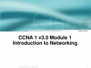
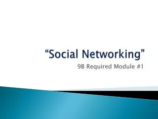
Secondary Private VLAN Types • Three types of Secondary PVLANs: • Promiscuous • A node attached to a port in a promiscuous secondary PVLAN may send and receive packets to any node in any others secondary VLAN associated to the same primary. Routers are typically attached to promiscuous ports. • Isolated • A node attached to a port in an isolated secondary PVLAN may only send to and receive packets from the promiscuous PVLAN. • Community • A node attached to a port in a community secondary PVLAN may send to and receive packets from other ports in the same secondary PVLAN, as well as send to and receive packets from the promiscuous PVLAN. Host 1 155 Host 2 17 Host 3 5 Host 4 Host 5 Host 6 vSphere 4- Mod 4 - Slide
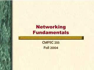
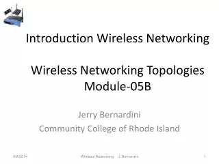
5 155 17 5 Private VLAN Implementation • Standard 802.1Q Tagging • No Double Encapsulation • Switch software decides which ports to forward the frame, based on the tag and the PVLAN tables VLAN 5 PVLAN 5 (Promiscuous) PVLAN 17 (Community) PVLAN 155 (Isolated) vSphere 4- Mod 4 - Slide
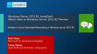
Why Private VLANs ? Problem • Why PVLANs? (examples) • Machines can be violated/infected, and can be used as a bridge for violating/infecting other machines in the same network segment • Attacks like ARP poisoning are still a danger, and port-security type of defence does not work well with ESX (For example in case of VMotion, if you set port-security to allow a maximum of X different MAC addresses, when you VMotion a VM that happens to be the X+1th, you’ll lose connectivity) • Segmentation of each and every host in the network is required Internet Gateway/Serer Infected Machine, acting as a bridge to infect others Victim sends traffic to the rogue instead of the gateway Rogue machine performing ARP Poisoning impersonating the gateway Machine that would not be reachable from Internet vSphere 4- Mod 4 - Slide
Why Private VLANs ? Solutions Solutions: • One VLAN per host or group of hosts • CONS: • A a lot of subnets of the /30 type, with waste of IP addresses (50%) • Consequently, lot of routes, which are difficult to maintain and change • Complex and expensive gateway (firewall) rules • Available VLANs are 4095*, but switches allow much less, about 1000 • Too complex/expensive to maintain • One VLAN per VM, with one VM acting as transparent/software bridge with firewall, thus on the same subnet • Can be implemented inside ESX 3.x • Even more complexity/cost • PVLAN vSphere 4- Mod 4 - Slide
Private VLANs: Example without PVLANs Example: Hosting company: • Many different customers that should not be able to “see” each other • Possible solution: • One VLAN per customer, but: • Creating a VLAN for each customer is expensive: • One subnet per customer is required, gateway maintenance is a nightmare • If a customer grows in size, subnets might have to be changed (for example /30 to /29) • Physical switches can handle a limited amount of VLANs per switch (less than 4000) ISP Internet Gateway Several /30 Subnets For bigger Customers, /29 or /28 Subnets vSphere 4- Mod 4 - Slide