Download
1 / 16
160 likes | 174 Views
Beam Dump Design Dan Wilcox March 2012. Overview. Graphite Beam Dump 4m x 4m x 3.2m. Helium Vessel + Iron Plates. Upstream Iron Shield. Outer Iron Shield. Downstream Iron Shield. Energy deposition in beam dump has since increased to 780 kW. This iron plate was removed.

E N D
Beam Dump Design Dan Wilcox March 2012
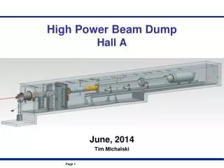
Overview Graphite Beam Dump 4m x 4m x 3.2m Helium Vessel + Iron Plates Upstream Iron Shield Outer Iron Shield Downstream Iron Shield
Energy deposition in beam dump has since increased to 780 kW This iron plate was removed Nikolas Vassilopoulos – NuFact 2011
Energy Deposition in Graphite Units W/m3
Thermal Analysis • Boundary condition: Two sides cooled to a constant 30°C. • Symmetry applied, one quarter modelled. • Mesh: quadratic hexahedral elements, maximum size 0.08m. • Properties based on graphite grade PSG-324, as used in the T2K beam dump. • The variation of thermal conductivity with temperature was taken into account. (To direction of extrusion)
Case 1: Solid Graphite Temperature in °C • Best case scenario, but impossible in practice • Results agree with hand calculation
Case 2: Graphite blocks, no heat transfer across gaps Temperature in °C • Worst case scenario for heat transfer • 0.4m x 0.4m extruded sections – similar to T2K
Case 3: Graphite blocks, helium conduction across gaps Temperature in °C • Assumed 2mm helium gaps – conservative • Assumed no convection – conservative
Structural Analysis • Sequential analysis – thermal then structural • Boundary condition: Each section was fully restrained at its outer face. • Loads: gravity, structural temperatures from thermal analysis • Symmetry applied, one quarter modelled. • The quadratic hexahedral thermal elements were converted to the equivalent structural elements. • The variation of mechanical properties with temperature was taken into account.
Stress Result – Von Mises Von Mises Stress in N/m2 • Maximum: 4.53MPa, occurring at the restraints • May be lower in practice due to deflection of restraints
Stress Result – 1st Principal 1st Principal Stress in N/m2 Von Mises Stress in N/m2 • Maximum tensile stress: 1.56MPa
Stress Result – 3rd Principal 3rd Principal Stress in N/m2 • Maximum compressive stress: 5.43MPa
Displacement Results X - Component Y - Component Maximum displacements; • δx; 3.3mm increase in length • δy; 0.63mm, -0.87mm • δz; 0.59mm, -0.80mm • Therefore no contact between adjacent blocks Z - Component
Failure Criteria Temperature • Rate of graphite oxidization increases with temperature. • Higher temperature means higher purity of helium required. • The limits set for T2K were; • 600degC: Helium should be < 30ppm O2, • 650degC: <10ppm O2 • (1 - 5% loss for 20yrs) Stress • Tensile tests were carried out at temperatures up to 900°C. • Tensile Strength: 7 - 8.5MPa (parallel), 4 - 5.5MPa (perpendicular) • Cf. Bending Strength: 14.7MPa (parallel), 9.8MPa (perpendicular) See “Status of the T2K Hadron Absorber Development - T.Ishida, 2006” for more details. (available online)
Conclusions • Max graphite temperature is expected to be somewhere between 425 and 575°C. • Based on T2K limits this is acceptable (Helium should be < 30ppm O2). • Graphite surface finish will have an important effect on heat transfer. • Tensile stress is not expected to exceed 1.56MPa. • This is well below the most conservative tensile strength limit of 4MPa. • The supporting frame should be designed to allow for expansion at the restraints. • Future work; • Consider contact between blocks • More accurate modelling of supports? • Specify cooling system requirements • Consider possibility of fatigue failure