Download
1 / 40
400 likes | 415 Views
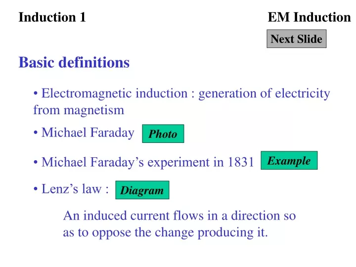
Induction 1. EM Induction. Next Slide. Basic definitions. Electromagnetic induction : generation of electricity from magnetism. Michael Faraday. Photo. Michael Faraday’s experiment in 1831. Example. Lenz’s law :. Diagram.

E N D
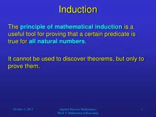
Induction 1 EM Induction Next Slide Basic definitions • Electromagnetic induction : generation of electricity from magnetism • Michael Faraday Photo • Michael Faraday’s experiment in 1831 Example • Lenz’s law : Diagram An induced current flows in a direction so as to oppose the change producing it.
Induction 2 EM Induction Next Slide Fleming’s right hand rule • Motion of a straight wire in a magnetic field can produce an induced current. • Fleming’s right hand rule Diagram • Moving-coil microphone Diagram • Magnetic tape recording and playback Diagram • Alternator Diagram • Dynamo Diagram
Transformer 1 EM Induction Next Slide Mutual Inductance • Mutual inductance in two soft-iron C-cores Diagram • Application : simple transformer (a.c. supply is used) Diagram • Example Diagram • Practical transformer Photo • Advantage in using transformer and a.c. Example
Transformer 2 EM Induction Next Slide Electrical Power in HK • Arrangement : generation, transmission and distribution Diagram • Discussion
Back to Induction 1 EM Induction Click Back to • Michael Faraday
coil N S magnet galvanometer Induction 1 EM Induction Next Slide • A coil is connected to a centre-zero galvanometer as shown in the following diagram. • A bar magnet is pushed into the coil and left for a few seconds. Then it is removed from the coil. • Flow of current in the coil would be indicated by the galvanometer.
Coil becomes a magnet direction of moving S N N S I : induced current Induction 1 EM Induction Next Slide • When the magnet is pushed into a coil, current flows in the coil. This current is called induced current.
N S The magnet remains at rest. Induction 1 EM Induction Next Slide • When the magnet is held motionless inside a coil, no current flows in the coil.
Coil becomes a magnet direction of moving S N N S I : induced current Induction 1 EM Induction Next Slide • When the magnet is pulled out of the coil, current flows in the opposite direction.
Back to Induction 1 EM Induction Click Back to • The experimental result is exactly the same except that the direction of the induced current is reversed when the polarity of the magnet is changed. • Induced current flows if the coil moves instead of the magnet. • Conclusion : an electromotive force (e.m.f.) is produced when there is relative motion between the coil and the magnet. • Induced e.m.f. can be increased by : (a) increasing the speed of the relative motion, (b) increasing the number of turns in the coil, and (c) using a stronger magnet
Coil becomes a magnet direction of moving S N N S I : induced current Induction 1 EM Induction Next Slide • Induced current changes the coil into a magnet such that a repulsive force is produced between the magnet and coil to oppose the motion of the magnet.
Coil becomes a magnet direction of moving S N N S I : induced current Back to Induction 1 EM Induction Click Back to • Induced current changes the coil into a magnet such that an attractive force is produced between the magnet and coil to oppose the motion of the magnet.
Motion (M) Magnetic field (B) Induced current (I) Induction 2 EM Induction Next Slide • Fleming’s right hand rule : The directions of current, magnetic and the motion of the conductor are represented by thumb, the first finger and the second finger respectively, if they are held perpendicular to each other. (IBMin short)
magnetic field motion S N induced current Back to Induction 2 EM Induction Click Back to • Application of Fleming’s right hand rule
Back to Induction 2 EM Induction Click Back to • Moving-coil microphone
Back to Induction 2 EM Induction Click Back to • Magnetic tape recording and playback
n N p A S B m q Induction 2 EM Induction Next Slide • In an alternator, a coil is made to rotate in a uniform magnetic field. As it rotates, induced current would be produced in the arms of the coil.
N S B A Induction 2 EM Induction Next Slide • Direction of induced current is shown.
Current (mA) 3/4 Time (no. of revolutions) 0 1/4 1/2 1 B A B A B B A B A A Induction 2 EM Induction Next Slide
n N p A S B m q Induction 2 EM Induction Next Slide • At t = 0, side A and B of the coil are parallel to the magnetic field, no induced current is produced. • From t = 0 to 1/4 no. of revolution, the induced e.m.f. increases from zero, reaching a maximum value at t = 1/4 no. of revolution, when the coil is horizontal. According to right-hand rule, the current flows from m n p q
n N p A S B m q Back to Induction 2 EM Induction Click Back to • From t = 1/4 to 1/2 no. of revolution, the induced e.m.f. decreases and the current still flows from m n p q. When t = 1/2 no. of revolution, the induced e.m.f. becomes 0. • From t = 1/2 to 3/4 no. of revolution, the current becomes reversed and flows in the direction q p n m. The induced e.m.f. increases from zero to maximum again when t = 3/4 no. of revolution.
n N p A S B m q Induction 2 EM Induction Next Slide • In a dynamo (d.c. generator), the half-rings of the commutator reverses the connection of the coil with the circuit.
Current (mA) Time (no. of revolutions) 0 1/4 1/2 3/4 1 B A B A B B A B A A Induction 2 EM Induction Next Slide
Back to Induction 2 EM Induction Click Back to • The induced e.m.f. and hence current, can be increased in alternator and dynamo by : (a) using a stronger magnet, (b) increasing the number of turns in the coil, (c) winding the coil on a soft-iron armature, (d) rotating the coil at a higher speed.
soft-iron core primary coil secondary coil Transformer 1 EM Induction Next Slide • A ring -shape soft iron core is used for the wiring of the primary coil and the secondary coil are • The primary coil is connected to a battery and a switch, the secondary coil is connected to a galvanometer.
B-field due to secondary coil soft-iron core primary coil secondary coil B-field due to primary coil Transformer 1 EM Induction Next Slide • When the switch is closed, the galvanometer gives momentary deflection.The rate of change in B-field is very great and hence current is induced in the secondary coil.
soft-iron core primary coil secondary coil B-field due to primary coil Transformer 1 EM Induction Next Slide • When the switch is kept closed, the galvanometer gives no deflection. Although B-field exists, there is no change in B-field and hence no current is induced in the secondary coil.
B-field due to secondary coil soft-iron core primary coil secondary coil B-field due to primary coil Transformer 1 EM Induction Next Slide • When the switch is opened, the galvanometer gives momentary deflection in the opposite direction as before.The rate of change in B-field is still great and hence current is induced in the secondary coil in opposite direction.
Back to Transformer 1 EM Induction Click Back to • This effect is called mutual inductance. • We can transmit current even there is no direction connection between two circuits, provided that the current is not stable.
primary coil a.c. supply secondary coil Transformer 1 EM Induction Next Slide • Now we connect an a.c. power supply to the primary coil so that an unstable current is maintained. A lamp is connected to the secondary coil. The lamp emits light since current is always induced in the secondary coil. This device is called transformer.
Transformer 1 EM Induction Next Slide • The relationship between the primary voltage and secondary voltage is given as : • The ratio of the secondary voltage to the primary voltage is equal to the ratio of the no. of turns in the secondary coil to the primary coil. • It means that the a.c. voltage can be easily changed to any desired value by using this kind of device. It is the advantage that using a.c. instead of d.c. in domestic circuit.
If , it is a step-up transformer that increases the p.d. of the a.c. • If , it is a step-down transformer that decreases the p.d. of the a.c. Step-up transformer’s symbol Step-down transformer’s symbol Transformer 1 EM Induction Next Slide
Back to Transformer 1 EM Induction Click Back to • Transformer is also an energy transmission device. However, the energy transmission is not 100% efficient.
200 V a.c. 12 V 24 W NP = 3000 Transformer 1 EM Induction Next Slide • A transformer has 3000 turns in its primary coil and is used to operate a 12 V 24 W lamp from the 200 V a.c. mains as shown in the following diagram. Assume the lamp is operated at the correct rating. (a) Find the number of turns in the secondary coil. (b) Find the current flow in the secondary coil. (c) Find the current flow in the primary coil if the effeciency is equal to (i) 100% (ii) 50%
Transformer 1 EM Induction Next Slide (a) Applying the transformer equation, The secondary coil has 180 turns. (b) The correct rating of the lamp is 12 V and 24 W, The current rating of the lamp is 2 A and so the secondary current is 2 A.
Back to Transformer 1 EM Induction Click Back to (c) (i) Power input = Power output The primary current is 0.12 A (ii) Power input = 2 Power output, The primary current is 0.24 A
Back to Transformer 1 EM Induction Click Back to • A practical transformer is shown in the following photo. • Soft iron core is used to trap the magnetic field. • Resistance of coils • Eddy currents in the core • Magnetization and demagnetization of core • Leakage of field lines
Transformer 1 EM Induction Next Slide 4 kW of power is supplied at the end of power cables of total resistance 5 . Calculate the power loss in the cables if power is transmitted (a) at 200 V, (b) at 4000 V. Solution : • The power loss is greatly reduced by transmitting the power at high voltage.
11 kV 220 V 400 kV overhead cables power station factory home 25 kV step-up transformer network of power cables step-down transformer Back to Transformer 2 EM Induction Click Back to • Power generation, transmission and distribution