Download
1 / 39
420 likes | 774 Views
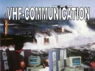
VHF Weak Signal Operation. by Marc C. Tarplee, Ph.D. N4UFP. What is “weak signal” operation?. Exactly what its name implies – operation at low signal-to-noise ratios It does not include the following modes/types of operation: FM, ATV Packet, RTTY, PACTOR

E N D
VHF Weak Signal Operation by Marc C. Tarplee, Ph.D. N4UFP
What is “weak signal” operation? • Exactly what its name implies – operation at low signal-to-noise ratios • It does not include the following modes/types of operation: • FM, ATV • Packet, RTTY, PACTOR • To understand VHF weak signal operation, one needs to understand two things: • VHF propagation • VHF operating modes
VHF Weak Signal Operation • VHF weak signal operation uses a variety of propagation techniques: • Tropospheric scatter • Tropospheric ducting • Sporadic E • Meteor Scatter • Auroral backscatter • F-Layer propagation • Moonbounce • The following modes are used in VHF weak signal operation: • CW, HSCW • SSB • FSK-441, JT6M • JT65 • VHF weak signal communications take place primarily on the 6m (50 MHz), 2m (144 MHz), and 1.25m (222 MHz) bands
Tropospheric Propagation Modes • Tropospheric Scatter • Variations in the humidity of the troposphere cause RF to be scattered over the horizon. This is known as tropospheric scatter • Tropospheric Ducting • Temperature inversions (warm dry air located above cool moist air) refract RF in the VHF range back towards the earth. Temperature inversions occur daily in the middle latitudes at sunrise and sunset. Communications are possible over a ranges up to 600 miles • Over the oceans, stable temperature inversions can create a duct, through which VHF can travel without significant loss up to 2500 miles • Ducting is most effective for signals in the high VHF and UHF region
Tropospheric Scatter Tropospheric Ducting
Sporadic E (ES) • Sporadic E (ES) • Clouds of high density ionization form without warning in the ionosphere’s E layer • ES is not dependent on solar activity. It may occur any time, but is most frequent between May and August, with a smaller peak of activity in December • Single hop ES has a range of ~1400 mi • Double hop ES has a range of ~ 2500 mi • Sporadic E is most common on 6m (about 1 day in 3 during the summer), rare on 2m and almost unknown on 1.25m • Cause of Sporadic E is not known: high altitude wind shear may be responsible.
Meteor Scatter • As meteors are vaporized in the upper atmosphere, they leave behind ionized trails at heights of 60 – 70 miles that are sufficiently dense to reflect VHF • A long trail lasts only 15 seconds – most trails are less than 1 second long • Scattering of higher frequencies requires denser trails. • Large meteors that produce denser trails are relatively rare • The trail density decreases with time • Meteor scatter is much less effective on 2m and 1.25m than 6m • Best time for meteor scatter is between midnight and 6:00 AM or during a meteor storm. • Because the direction of arrival of meteors is not random, best scattering results generally occur when the antennas are pointed slightly to one side of the true bearing.
Auroral Backscatter (Au) • In the upper atmosphere above both poles, there are doughnut shaped regions of charged particles that cause the aurora borealis (and aurora australis) • This region results from the interaction of the solar wind, the earth’s atmosphere, and the earth’s magnetic field. • A solar flare can cause the auroral zone to increase in density and expand, making it capable of scattering VHF signals without significant absorption. • RF interacts strongly with the aurora, resulting in significant distortion of the signal. Only narrow band modes such as CW are used during Au openings
F-Layer Propagation • F2 Layer Propagation • Communications over long distances (> 2000 miles) are possible on 6 m via the F2 layer of the ionosphere during periods of high solar activity (solar flux above 220) • Openings generally occur in spring and fall during daylight hours (similar to 10 m) • F2 propagation does not occur on the higher VHF bands. • Transequatorial F • The ionosphere’s F layer is most intense in the region of the geomagnetic equator. • Stations within about 2500 miles of the geomagnetic equator can launch VHF signals into these regions. The RF is refracted and travels across the equator and into the other hemisphere without scattering from the ground • Stations using TE must be at approximately equal distances from the geomagnetic equator • Like F2 propagation, Transequatorial F occurs only on 6m
F-Layer Path Geometries Transequatorial F F2 Propagation
Moonbounce • The moon is used as a reflector for VHF signals • Communications are possible between any two stations which can see the moon simultaneously • Path losses are very high (> 250dB)
CW Used on all VHF bands • Used specifically for the following modes: • Tropospheric scatter • Auroral backscatter • CW activity occurs primarily in the following band segments: • 50.080 – 50.100 MHz • 144.150 – 144.200 MHz • 222.000 – 222.200 MHz • Frequencies near 50.100, 144.200, and 222.100 MHz are used as calling frequencies. • If the band is active, stations move off the calling frequency and spread down the band.
HSCW • CW sent at high speeds (200 wpm or more) • Used primarily for meteor scatter • Is being phased out in favor of new digital modes • Most QSO’s are made via sked using defined protocols • HSCW activity occurs primarily in the following band segments: • 50.250 – 50.300 MHz • 144.100 – 144.150 MHz • 222.000 – 222.200 MHz
SSB • Widely used for: • sporadic E communications • tropospheric ducting communications • Can be used for auroral backscatter communications on 6m. • Each band has a defined SSB calling frequency • 6m – 50.125 MHz (USA) 50.110 MHz (DX) • 2m – 144.200 MHz • 1.25m – 222.100 MHz • Operation begins on or near these frequencies and spreads up the band conditions improve
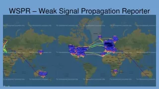
FSK-441 • FSK441 • Uses triplets of 4 tones to transmit data • 882, 1323, 1764, 2205 Hz • Each character is sent as a 3 tone sequence • 43 Character alphabet (letters, numbers . , / ? # $ <sp>) • Single tone characters used for shorthand messages: • 882 Hz - R26 1764 Hz - RRR • 1323 Hz – R27 2205 Hz - 73 • Data rate = 147 characters per second (3 tones/char) • Used for meteor scatter communications • Most activity takes place near 50.270 MHz
FSK-441 Protocols • Messages sent in 30 sec intervals – westernmost station transmits during first 30 seconds of each minute. • A complete FSK441 QSO consists of exhange of call signs, signal reports and rogers by both stations • Message sequence • 1. both call signs (ex: N0ABC N4UFP) • 2. call signs plus signal report (ex: N0ABC 26 N4UFP 2626) • 3. roger + report (ex R27 R27) • 4. final roger (RRR RRR) • Both stations begin by sending both call signs. • First station to copy both call signs sends calls plus signal report. • When other station receives calls + signal report, he sends roger + his report • When first station receives roger + report, he sends his roger. • Final exchange of “73” is optional • Time to complete a QSO ranges from 2 minutes to over an hour.
JT6M • 44 tone MFSK • 43 tones for characters 1099.19 – 2002.59 Hz (Df ~ 21.53 Hz) • 1 tone for synchronization (1077.66 Hz) • Each tone sent for 46.44 msec • Effective data rate = 14.4 characters/second • Requires a stable receiver, good timing • Can copy signals when SNR < 0 • Ideal for troposcatter, meteor scatter and moonbounce on the 6 meter band.
JT6M Protocols • Messages sent in 60 sec intervals – westernmost station transmits during even-numbered minutes. • Message sequence • 1. both call signs (ex: N0ABC N4UFP…) • 2. call signs plus signal report (ex: N0ABC N4UFP OOO…) • 3. roger + report (ex RO RO…) • 4. final roger (RRR RRR…) • 5. 73’s (73 73 73) • Signal report OOO means signal is readable – it is the only valid JT65 signal report • QSO’s require at least several minutes to complete. • Most activity takes place near 50.270 MHz, generally by sked.
JT65 • 65 tone MFSK with Reed-Solomon coding • ~5.4 Hz operating bandwidth • 100% copy is possible at SNR < -10dB • Message sequence • 1. both call signs (ex: N0ABC N4UFP…) • 2. call signs plus signal report (ex: N0ABC N4UFP OOO…) • 3. roger + report (ex RO RO…) • 4. final roger (RRR RRR…) • 5. 73’s (73 73 73) • Signal report OOO means signal is readable – it is the only valid JT65 signal report
VHF Station Requirements • Terrestrial Modes • RF output at least 100 W • Good VHF transceiver or transverter with MDS of -136 dBm (3 KHz BW) • Mast-mounted pre-amp, gain > 10 dB • Horizontally polarized beam antenna, gain > 10 dB • Moonbounce. • RF output at least 500W • Good VHF transceiver or transverter with MDS of -136 dBm (3 KHz BW) • Mast-mounted pre-amp, gain > 10 dB • beam antenna, gain > 15 dB with az-el rotator
Operating Notes – Troposcatter and Tropospheric ducting • Listen near calling frequencies for activity before scanning the band. • Troposcatter signals are generally weak (typically < 2 s-units) and subject to slow fades over 30 sec or so. • QSO information should be sent quickly while signal levels are up. • Tropo ducting signals are moderately strong and relatively steady, but quickly disappear when the duct deteriorates
Operating Notes – Sporadic E • Listen near calling frequencies for activity before scanning the band. • Sporadic E signals can be very strong (> s9), but may suddenly disappear • QSO information should be sent quickly while signal levels are up. • As the opening develops, general operating practice is for SSB stations to spread up from the calling frequency and for CW stations to spread down. • Do not use the 6m DX window (50.100 – 50.125 MHz) for domestic contacts during a band opening
Operating Notes – Meteor Scatter • Most meteor scatter operation is done using the FSK-441 or JT6M modes. • Time synchronization is important – be sure to set your PC’s clock to WWV before beginning a MS contact. • Random contacts can be made (especially on 6m) by calling CQ on the calling frequency, but most contacts are made via sked. • When calling CQ: • Transmit during the first 30 sec period when beaming in an easterly direction • Transmit during the second 30 second period when beaming in a westerly direction • MS contacts may be made at any time, but the best time is in the early morning hours (before 6:00 AM)
Operating Notes – Meteor Scatter • Links to MS QSO scheduling sites • http://www.pingjockey.net/ • http://www.dxworld.com/hsms.html
Useful Tools • General Meteor Scatter Info • http://www.qsl.net/w8wn/hscw/hscw.html • Aurora Info • http://aurora.n1bug.net/ • Tropospheric propagation prediction tools: • VHF Propagation from APRS data • William Hepburn’s Tropo Forecasts
VHF Antennas • VHF antennas are relatively small, light and easily rotatable. • Best choices for a new operator: • Quad (at least 2 el on 6m, 5 or more elements on 2m and 1.25m) • Yagi (at least 3 el on 6m, 5 or more elements on 2m and 1.25m) • For weak signal work (CW/SSB) the antenna should be horizontally polarized • For EME an array of 4 long yagis is typical • Meteor scatter operation requires an antenna with good gain and broad beamwidth – 5 to 9 element yagis work well.
6 Meter Quad and Yagi Antennas • 2 element Quad (square loops of #14 ins. wire Z ~ 60 ohms Gain ~ 4 dBd) • Element Loop Length (in) Position (in) • Reflector 245.0 0 • Driver 235.5 29 • 3 element Yagi (Aluminum tubing Z ~ 42 ohms gain ~ 5 dBd) • Element Half Length (in) (0.75 dia 0.625 dia) Position (in) • Reflector 24 35.875 0 • Driver 24 31.875 50 • Director 24 26.375 87 • 5 element Yagi (Aluminum tubing Feed Z ~ 35 ohms Gain ~ 8 dBd) • Element Half Length (in) (0.75 dia 0.625 dia) Position (in) • Reflector 24 35.875 0 • Driver 24 33.875 49 • Director 1 24 30.000 72 • Director 2 24 29.500 121 • Director 3 24 28.000 169
2 Meter Yagi Antennas • 5 element Yagi (0.188 dia Al rod Feed Z ~ 40 ohms Gain ~ 8 dBd) • Element Half Length (in) Position (in) • Reflector 20.625 0 • Driver 20 17 • Director 1 18.625 25 • Director 2 18.5 42 • Director 3 17.875 59 • 8 element Yagi (0.188 dia Al rod Feed Z ~ 40 ohms Gain ~ 11 dBd) • Element Half Length (in) Position (in) • Reflector 19.875 0 • Driver 19 16 • Director 1 18.25 26 • Director 2 18. 49 • Director 3 17.625 80 • Director 4 17.5 113 • Director 5 17.375 146 • Director 6 16.875 178
1.25 Meter Yagi Antenna • 8 element Yagi (0.125 dia Al rod Feed Z ~ 40 ohms Gain ~ 11.5 dBd) • Element Half Length (in) Position (in) • Reflector 12.6875 0 • Driver 12.4375 10.5 • Director 1 11.9375 18 • Director 2 11.8125 32 • Director 3 11.5 51.5 • Director 4 11.375 73 • Director 5 11.3125 95 • Director 6 11.25 115
VHF Operating Activities • Contests • ARRL January VHF Sweepstakes (3rd weekend in January) • ARRL June VHF QSO Party (2nd weekend in June) • SMIRK QSO Party (3rd weekend in June • CQ WW VHF Contest (2nd weekend in July) • Six Club 6 m Sprint (3rd weekend in July) • ARRL September QSO Party (2nd weekend in September) • Operating Awards • VUCC – contacts with 100 Grid Squares, not difficult • WAS – tough, but not impossible • DXCC – very tough from North America, but it has been done • Grid Square Hunting • There are over 500 grid squares in the continental US • No one has worked them all yet (except perhaps for W5FF)
What is a Grid Square? • Almost all VHF operating awards and contests involve grid squares • Grid Squares are 2º longitude x 1º latitude sections of the earth’s surface (there are 32,400 in total) • Each grid square has a 4 character designator containing 2 letters and 2 numbers. • The two letters designate the field. There are 324 fields lettered AA through RR • Each field is divided into 100 squares numbered 00 through 99 • The continental US includes grid squares in fields CM,CN, DL, DM, DN, EL,EM,EN, FM and FN • Most of Rock Hill is in grid square EM94.