Download
1 / 11
170 likes | 430 Views
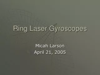
R. . CCW. CW. А 1. А 2. Fig.2.1. RING LASER GYROSCOPES. Sagnac Effect

E N D
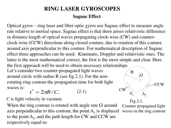
R CCW CW А1 А2 Fig.2.1. RING LASER GYROSCOPES Sagnac Effect Optical gyros – ring laser and fiber optic gyros use Sagnac effect to measure angle rate relative to inertial space. Sagnac effect is that there arises relativistic difference in distance length of optical waves propagating clock-wise (CW) and counter-clock-wise (CCW) directions along closed couture, due to rotation of this couture around axis perpendicular to this couture. For mathematical description of Sagnac effect three approaches can be used: Kinematic, Doppler and relativistic ones. The latter is the most mathematical correct, the first is the most simple and clear. Here the first approach will be used to obtain necessary relationships. • Let’s consider two counter-propagated light waves around circle with radius R (see fig.2.1). For the non-rotating ring contour the propagation time for both light waves is: (2.1) С is light velocity in vacuum. When the ring contour is rotated with angle rate around axis perpendicular to this contour, the point A1 is displaced to the point A2, and the path length for CW and CCW are respectively equal to: Counter propagated light waves in the ring contour
(2.2) Propagation time for CWW and CW is: (2.3) Time difference is defined as: (2.4) Difference in length for CWW and CW is: (2.5) Square of the contour is S = R2, so the following relationship can be obtained: (2.6) Phase difference for CWW and CW is defined as: (2.7) Here is the wave length, and s – Sagnac phase. In order to register Sagnac phase two light waves are combined to interfere. Interference pattern fringe displacement during rotation is proportional to Sagnac phase and taking into account expression (2.7) to angle rate measured, .
Fig. 2.2 For using this method in practice the sensitivity of the Sagnac method should be increased. The simplest technique to increase sensitivity of this method is increasing the square of the closed contour. If this contour is formed from optical fiber of length L wounded on the coil with radius R, then Sagnac phase is defined as: (2.8) Here N and Sware the number of fiber cable windings on the coil and square of the one winding, respectively. This technique to increase sensitivity of Sagnac method resulted in creation of fiber optic gyro (FOG) . With the development of integrated optic technology some parts of FOG have been implemented in view of small-sized solid state design with use of planar optical technology, and fiber optic multi-winding coil was replaced for thin film waveguide, for example, from titanium which is deposited on the substrate made of lithium niobate. This technology resulted in creation of integrated optical gyro existing now in hybrid implementation which due to its mini size is called micro-optical gyro. Sagnac method sensitivity increasing can be made by transferring from phase to frequency measurements. For this, optical ring resonator should be formed with the aid of reflecting elements – mirrors or prisms (see fig.2.2).
Resonant frequency of the resonator is defined by optical path length and amplifies radiation wave length of which is multiple to double length of the resonator L = q/2, q is integral number. At this condition there is a standing wave in the resonator which nodal points are fixed on the reflecting surfaces of the resonator (mirrors). In absence of resonator rotation counter propagated waves have equal optical path length. When resonator is rotated and projection of angle rate on the straight line perpendicular to resonator plane is not equal to zero, due to Sagnac effect the difference of optical path for counter propagated waves appears, hence resonant frequency for these waves is split and resonator amplifies different frequency, f, from the laser radiation spectrum. Difference frequency for rotating resonator is defined as: (2.9) From these expressions, taking into account (1.6), obtain: (2.10) Thus, it can be seen that difference frequency of counter propagated waves in the optical resonator is proportional to angle rate with coefficient of proportionality (scale factor) k = 4S/L. Let’s suppose that optical resonator has equilateral triangle form with the side 10 cm, for wave length = 0.63 µm for ring laser gyro scale factor of the value k = 9104 Hz/(rad/s) 0.45 Hz/(arc sec/sec) can be obtained.
Fig.2.3. Standing wave in RLG. In 1962 A. Rosental proposed He-Ne laser with ring resonator and by this opened the history of ring laser gyroscope development and together with it modern optical gyroscopy. Though at present time there are many deferent optical schemes of laser gyros: gas, solid state, operating in one-, two- and multimode generation regimes; with linear and circular light polarization etc., the best, from practical point of view, is He-Ne laser with wave length = 0.63 µm operating from direct current.Such a laser operates in continuous regime of radiation, it has sufficient amplification coefficient, high life time, consumes low power and can be made rigid and compact. RLG modes disposition. Operation principal of He-Ne laser is widely highlighted in scientific literature, here we note that at propagation of laser radiation in ring resonator with length L from the spectrum of laser radiation only waves with resonant frequency of the resonator are amplified, namely the wavelength for which the relationship L = q/2 is valid.This is the condition of laser radiation generation. At this condition there appears a standing wave (see fig.2.3). Such oscillations are called natural oscillations (modes) of the resonator and they form equidistant spectrum of natural modes q = qC/2L, q=1…n.
G n ( ) C/2L Dn p ... ... n n n n q q +1 12 Fig.2.4. RLG modes disposition. Damping of the standing wave in resonator is due to its non-ideality and results in energy loss. Energy loss in optical resonator is due to transmission and absorbing of the resonator mirrors because of diffraction on the ends of the mirrors and mirror adjustment errors as a result a part of reflected light from one mirror does not get to the other one and is absorbed by walls of the resonator. As a result the resonator has bandwidth of approximately equal to r= 2 MHz, and total losses are usually no greater than 2%. Figure 2.4 presents dependences of amplification coefficient of active laser medium (He-Ne gas mixture) on frequency G(), the losses line and resonator natural mode spectrum. Generation can be carried out only for that modes for which the condition G() > is valid. Standing wave in fig.2.3 can be interpreted as angle scale relative to which angle turn measurement is produced. In ideal case the frequency of counter propagated waves is proportional to angle rate measured: f = k (2.11) Coefficient k is the scale factor of the RLG. It is defined by the expression (2.10).
f W Fig.2.5.Output characteristic of ideal RLG. f f s W W s Fig.2.6. RLG Bias. The dependence (2.11) is called output characteristic of ideal RLG. It is depicted in fig.2.5. However output characteristic of real RLG differs from ideal one. At small angle rate it is essentially nonlinear one, there are a dead zone and bias (zero shift) and also instability of the characteristic in time, from turn-on to turn-on and under changing of environmental conditions. RLG Bias Zero shift of the gyro output characteristic called bias is due to nonreciprocal changing of refraction coefficient of the medium for counter propagated waves in the ring resonator which is caused by any other reasons, but rotation. Thus, expression for output characteristic is written as: f = k( +s ). (2.12) In gas discharge providing inversion population of energy levels in He-Ne laser bias arises for the account of directed drift of electrons, positive ions and neutral atoms, so-called Langmuir drift of Ne atoms being in exciting condition. Usually, RLG bias is in the range of [0.1…1] deg/h and RLG output characteristic with bias is presented in fig.2.6.
f Region of linearity Region of linearity W W0 2Wc Fig.2.7. Output characteristic of a real RLG. RLG Dead Zone Under RLG rotation with angle rate less, than certain threshold c, counter propagated waves frequencies are synchronized and their difference frequency becomes equal to zero. This phenomenon is referred to as synchronization or lock-in of counter propagated waves. It occurs due to couple of counter waves through back scattering of the laser mirrors. As a result part of wave energy is scattered to the propagation direction of another wave and under such counteraction the phase and frequency of each wave is changed. The value defining the synchronization (lock-in) threshold of RLG can be calculated as follows: fc = r2 CE2 / 2LE1. ; c=fc/ K, (2.13) • Where E1, E2 are intensity of counter propagated waves; r2 is the back scattering coefficient of the mirror. Coefficient r2characterizes mirror quality, its flatness. When angle rate measured is less, than c=fc/k, the difference frequency is not observed. Out of the RLG dead zone when || > c output characteristic can be presented by the expression:
Mirror surfaces Counter propagated beams from RLG resonator A A interference fringes X3mm d A prism X FD o <0 >0 A d 90 + Fig.2.8. RLG output frequency read-out. 0 , when <c RLG output signal = when >c (2.14) k(+s), when >>c Practical RLG lock-in threshold is in the range [100....1000] Hz which for k=0.5 Hz/(arc sec/sec) corresponds to 200…2000 deg/h. RLG Output Information Read-Out RLG counter propagated waves’ difference frequency is measured by combining these waves on the sensitive square of the photodiode. For this, one of the mirrors transmits 0.1% of the light energy to output a part of counter propagated waves from the resonator. Under combination of light radiation, the two rays should be almost parallel to each other to interfere on the sensitive square of the photodiode. It is often made by the use of additional prism.Fig.2.8 presents one of the practical schematic for combination of the two rays. If angle in the vertex of the prism is close to 90 deg, for example, 90+, where is small angle, then there is interference pattern on the sensitive square of the photodiode as depicted in the fig.2.8 cut A-A.
Dx/4 I PD1 PD2 I(t) PD1 signal PD2 signal X Fig. 2.9. Photodiode disposition X Fig. 2.10. Phase deference between PD1 and PD2 signals is /2. Interference fringes disposition on the square of the photodiode is dependent on angle and in the case when intensity of the two rays is equal to I0, the intensity of interference fringes can be described by the expression: I(t) = I0 [1 + cos(2x/ + t +* )] . (2.15) Here =2πf, * is a constant phase shift, x is coordinate in the plane of photodiode perpendicular to interference fringes. Thus, in absence of rotation (= 0) interference pattern is stationary (unmovable). Under RLG rotation ( 0) the difference frequency appears and interference pattern moves along coordinate x with the velocity proportional to . The distance x/4 between fringes is defined by the expression x= /2n, where n is refraction index of the prism material. For angle = 15 arc sec, =0.63 µm, n=1.5 the distance between the fringes is equal to x = 3 mm. From the equation (2.15) follows that rotation direction is defined by direction of fringes motion. Using two photodiodes shifted relative to each other by the value of x/4 (see fig. 2.9) the direction of fringes motion can be defined using phase difference information from photodiodes PD1 and PD2 signals as depicted in fig.2.10.
RLG with such read-out schematic is the rate integrated gyro with discrete output signal that can be seen from equation (2.1) which after integration over time of its both sides gives: N(t)= k(t) , (2.16) Where N(t) is the number of photocurrent pulses for time t, and (t) is the angle turn for time t. Reversible count of the photocurrent pulses for time t gives total turning angle for this time interval independent on angle rate. Proceeding from the expression (2.16), scale factor dimensionality is[k] = pulse/arc.sec, so we have for practical RLG k = 0.45 pulse/arc.sec = 9 104 pulse /rad.