Download

1 / 59
600 likes | 670 Views
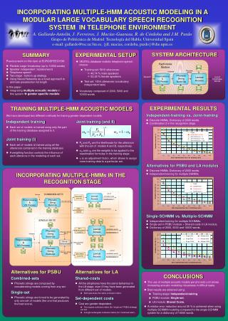
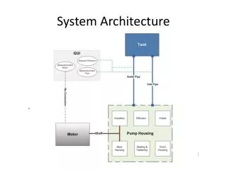
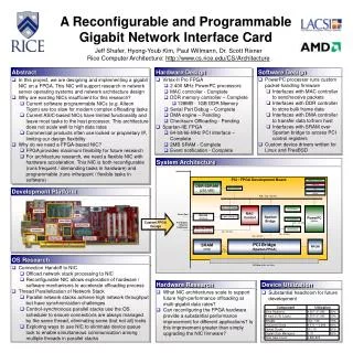
SYSTEM ARCHITECTURE OF ZXJ10(V10.0). OVERALL SYSTEM STRUCTURE. MP. THE FEATURES OF THE ZXJ10 SWITCH. RSM. MSM. RLM. PSM. PSM. SNM. RSM. RLM. PSM. RLM. OMM. TCP/IP. Network Diagram. FOREGROUND. RSM. MSM. PSM. PSM. RLM. SNM. RSM. RLM. PSM. RLM. MP. TCP/IP. BACKGROUND.

E N D
MP THE FEATURES OF THE ZXJ10 SWITCH RSM MSM RLM PSM PSM SNM RSM RLM PSM RLM OMM TCP/IP
Network Diagram FOREGROUND RSM MSM PSM PSM RLM SNM RSM RLM PSM RLM MP TCP/IP BACKGROUND OMM
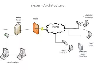
The Structure of Background Network WIN2000 Server MP MP Protocol TCP/IP Router Client Client .. DDN PSTN/PSPDN Client Client Client
THE FEATURES OF THE ZXJ10 SWITCH MODULAR SYSTEM STRUCTURE • Switching Network Module (SNM) • Message Switching Module(MSM) • Operation and Maintenance Module (OMM) • Peripheral Switching Module (PSM) • Remote Switching Module (RSM) Central module
THE FEATURES OF THE ZXJ10 SWITCH -----The Multi-module Forms an Exchange. With a 2-level or 3-lever Networking Capability, Module Can Further Carry Modules. • Two Cases: • Level -1 Is Central Module • Level -1 Is PSM
THE FEATURES OF THE ZXJ10 SWITCH ----CENTRAL MODULE. Central module 1-level PSM RSM RSM 2-level PSM RSM RSM 3-level RSM RLM
THE FEATURES OF THE ZXJ10 SWITCH ----A SINGLE PSM 1-level PSM RLM 2-level RSM PSM 3-level RSM RSM RLM RLM RLM
THE FEATURES OF THE ZXJ10 SWITCH PSM Access Way Fiber Bus Interface (FBI board RSM Access Way Digital Trunk Interface (DTI) Board Optical Digital Trunk(ODT) Board Built-in SDH
THE FEATURES OF THE ZXJ10 SWITCH Fully Distributed Control Mode Units have their own separate control modules while the MP supervises the overall control of all the different units.
MAIN FUNCTIONS OF A PSM In the Single Modules Office ,It Performs the PSTN,ISDN Subscriber Access and Call Handling, In a Multi-module Office ,It Is Connected Into the Central Module As One of the Module Offices .
Control cabinet #0 Subscriber cabinet #1 Subscriber cabinet #2 Subscriber cabinet #3 Subscriber cabinet #4 PSM cabinets
1 2 3 4 5 6 7 8 9 10 11 12 13 14 15 16 17 18 19 20 21 22 23 24 25 26 27 P O W B P O W B D T I D T I D T I D T I D T I D T I D T I D T I D T I D T I D T I D T I D T I D T I D T I D T I D T I D T I D T I D T I D T I D T I D T I D T I D T I D T I D T I D T I A S I G A S I G A S I G A S I G P O W B P O W B 1 1 1 1 1 2 2 2 2 2 3 3 3 3 3 4 4 4 4 4 5 5 5 5 5 6 6 6 6 6 7 7 7 7 7 8 8 8 8 8 9 9 9 9 9 10 10 10 10 10 11 11 11 11 11 12 12 12 12 12 13 13 13 13 13 14 14 14 14 14 15 15 15 15 15 16 16 16 16 16 17 17 17 17 17 18 18 18 18 18 19 19 19 19 19 20 20 20 20 20 21 21 21 21 21 22 22 22 22 22 23 23 23 23 23 24 24 24 24 24 25 25 25 25 25 26 26 26 26 26 27 27 27 27 27 P O W B S M E M MP MP C O M M C O M M C O M M C O M M C O M M C O M M P E P D M O N P O W B P O W B C K I S Y C K S Y C K D S N D S N D S N I D S N I D S N I D S N I D S N I D S N I D S N I D S N I F B I F B I P O W B P O W A P O W A S L C S L C S L C S L C S L C S L C S L C S L C S L C S L C S L C S L C S L C S L C S L C S L C S L C S L C S L C S L C S L C S L C S L C S L C S L C S L C S L C S L C S L C S L C S L C S L C S L C S L C S L C S L C S L C S L C S L C S L C M T T S P S P I S P S P I P O W A P O W A 8K SWITCHING MODULE B D T 6 B D T 5 B C T L 4 B N E T 3 B S L C 2 B S L C 1
1 2 3 4 5 6 7 8 9 10 11 12 13 14 15 16 17 18 19 20 21 22 23 24 25 26 27 POWERA POWERA POWERA SLC SLC SLC SLC SLC SLC SLC SLC SLC S L C S L C S L C SLC SLC SLC SLC SLC SLC SLC SLC SLC SLC SLC SLC SLC SLC SLC SLC SLC SLC SLC SLC SLC SLC SLC SLC SLC SLC SLC SLC SLC SLC SLC SLC SLC SLC SLC SLC SLC SLC SLC SLC SLC SLC SLC SLC SLC SLC SLC SLC SPI SPI SPI SPI SPI SPI POWERA POWERA POWERA POWERA POWERA POWERA SLC SLC SLC SLC SLC SLC SLC SLC SLC S L C S L C S L C SLC SLC SLC SLC SLC SLC SLC SLC SLC SLC SLC SLC SLC SLC SLC SLC SLC SLC SLC SLC SLC SLC SLC SLC SLC SLC SLC SLC SLC SLC SLC SLC SLC SLC SLC SLC SLC SLC SLC SLC SLC SLC SLC SLC SLC SLC SLC SLC MTT MTT MTT SP SP SP SP SP SP POWERA POWERA POWERA
THE STRUCTURE OF THE PSM • PSM Consists of the Following Basic Parts: • Switching Unit • Subscriber Unit • Digital Trunk Unit • Analog Signaling Unit • Control Part • Synchronization Part
THE STRUCTURE OF THE PSM Control part • A Pair of Active and Standby MP • Shared Memory Board(SMEM) • Communication Board(COMM) • Monitor Board(MON) • Peripheral Environment (PEPD)
1 2 3 4 5 6 7 8 9 1 1 1 1 1 1 1 1 1 1 2 2 2 2 2 2 2 2 0 1 2 3 4 5 6 7 8 9 0 1 2 3 4 5 6 7 P S S S S S S S S S S S S S S S S S S S S S S P O L L L L L L L L L L L L L L L L L L L L P P O W C C C C C C C C C C C C C C C C C C C C I I W A 1 2 3 4 5 6 7 8 9 1 1 1 1 1 1 1 1 1 1 2 A 0 1 2 3 4 5 6 7 8 9 0 P S S S S S S S S S S S S S S S S S S S S M S S P O L L L L L L L L L L L L L L L L L L L L T P P O W C C C C C C C C C C C C C C C C C C C C T W A 1 2 3 4 5 6 7 8 9 1 1 1 1 1 1 1 1 1 1 2 A 0 1 2 3 4 5 6 7 8 9 0 THE STRUCTURE OF THE PSM Subscriber line unit
THE STRUCTURE OF THE PSM Subscriber line unit • 2 SP:Active/standby • 2 SPI(SP interface);active/standby • MTT(multi-task test board):used for subscriber line test • Max.40 SLC(subscriber line circuit) • Each SLC board can provides 24 subscriber lines • A subscriber unit occupies 2 HWs and 2 Comm. ports
THE STRUCTURE OF THE PSM Digital trunk unit
THE STRUCTURE OF THE PSM Digital trunk unit The Digital Trunk Unit Is the Interface Unit Between the Digital Switching System or Between Digital SPC Switches and Digital Transmission Devices. A B DT DT PCM 2Mb/s
THE STRUCTURE OF THE PSM Digital trunk unit • One DT unit only has one DTI board • One DTI board has 4 PCM (sub-unit) DTI PCM1 Provide 120 digital trunk subscribers for every board PCM2 PCM3 PCM4
THE STRUCTURE OF THE PSM Analog signaling unit • One Analog signaling unit only has one ASIG board. • ASIG board can be configured as • ---DTMF function • ---MFC function • ---TONE function • ---CID function • ---Conf. function
1 2 3 4 5 6 7 8 9 1 1 1 1 1 1 1 1 1 1 2 2 2 2 2 2 2 2 0 1 2 3 4 5 6 7 8 9 0 1 2 3 4 5 6 7 P C S S D D D D D D D D D D F F P O K Y Y S S S S S S S S S S B B O W I C C N N N N N N N N N N I I W B K K I I I I I I I I B B B C C T T L L THE STRUCTURE OF THE PSM Switching Network Layer
THE STRUCTURE OF THE PSM Switching Network Unit DSN Unit Can Handle Time Slot Switching of the Voice Channel. And Control Message Channel Constitution:2 DSN boards DSN DSN Work mode:active /standby
DIGITAL SWITCHING NETWORK • Main Function: • Performing Voice Channel Connection Switching of Subscribers Inside the Module; • Interconnected With Central Switching Network Module to Realize Inter-module Voice Channel Connection; • For Mp to Set up Message Switching Connection and Communication Via Semi-permanent Connections With Function Units;
HWS DISTRIBUTION OF DSN IN PSM • Each DSN board has 64 HWS. • A HW bus rate is 8Mb/s(128ts) • Each DSN board has a capacity of 8K*8K time slots
HWS DISTRIBUTION IN PSM Message communication 0 1 2 3 DSN 20 21 22 4 5 6 18 19 Connected with various units Inter-module connection 60 61 Standby HW line 62 63 Self-looping testing
Working Mode: Active/Standby standby active working active standby MP/DSN /DSNI-SP working
HWS DISTRIBUTION IN PSM Those Starting HW20 Upward Are Used for Connection With Subscriber Units. Each Subscriber Unit Seizes Two HW Lines; Those Starting Hw61 Downward Are Used for Connection With Digital Trunks and Analog Signaling Units. Each Unit Seizes One HW Line; Function SN. HW0~3 4HW Used for Message Communication HW4-19 16HW Used For Inter-module Connections HW20-61 42HW Used for Various Unit Connection Usually a Standby HW Line, Though It Can Also Be for Communication Between Units HW62 1HW HW63 1HW Used for Self-looping Testing
The Message Channel SNM or other PSM FBI DSNIC HW0至HW3 MP C O M M DSN DSNI-S function unit
DSNI-C (DIGITAL SWITCHING NETWORK INTERFACE BOARD) Function: An interface of MP level (MP- DSN) • It Drives the Various Signals Transmitted Between MP and DSN. • It Performs the Conversion of 8mb/s Data Stream and 2mb/s Data Stream. • A Pair of DSNI Boards Handle 4 HWs. MP--COMM--DSNI-C--DSN
DSNI-S (DIGITAL SWITCHING NETWORK INTERFACE BOARD) Function: An interface of SP level (SP – DSN) • It Drives Transmission Between Function Unit and DSN. • No Data Rate Conversion • A Pair of DSNI Boards Can Handle 16 HWs. SP--DSNI-S--DSN
THE VOICE CHANNEL Suppose one subscriber in one SLU call another subscriber in another SLU,the voice channel will be as follows. SP---DSNI---DSN(T-network)---DSNI---SP
FBI (Fiber Bus Interface) It Applies Synchronous Multiplexing Technique and Optical Fiber Technique to Implement the Interconnections of Modules . It Uses Two Optical Fiber Lines to Transmit up to 16 Lines of 8mb/s PCM Signals It Can Reduce Connection Wires and Increase Anti-interference Ability of the System, and to Reduce Mutual Cross Talks Among Wires.
THE STRUCTURE OF THE PSM Clock synchronous part Retrieving the reference clock from the superior exchange(DTI or FBI) ,it provides synchronization timing signals SYCK SYCK CKI Working mode:Active/standby
THE STRUCTURE OF THE PSM Clock synchronous unit • 2 SYCK boards • 1 CKI board SYCK(synchronization oscillator) According to the reference clock generates the synchronous clock for the module or system(PSM).
THE STRUCTURE OF THE PSM Clock synchronous unit CKI Function is to provide generate system clock in case of reference failure for SYCK.
B C T N P O W B S M E M M P M P C O M M C O M M C O M M C O M M C O M M C O M M P E P D M O N T N E T T N E T A S I G A S I G A S I G D T I D T I D T I D T I D T I P O W B 1 2 3 4 5 6 7 8 9 10 11 12 13 14 15 16 17 18 19 20 21 22 23 24 25 26 27 6 B S L C 5 1 1 1 1 1 2 2 2 2 2 3 3 3 3 3 4 4 4 4 4 5 5 5 5 5 6 6 6 6 6 7 7 7 7 7 8 8 8 8 8 9 9 9 9 9 10 10 10 10 10 11 11 11 11 11 12 12 12 12 12 13 13 13 13 13 14 14 14 14 14 15 15 15 15 15 16 16 16 16 16 17 17 17 17 17 18 18 18 18 18 19 19 19 19 19 20 20 20 20 20 21 21 21 21 21 22 22 22 22 22 23 23 23 23 23 24 24 24 24 24 25 25 25 25 25 26 26 26 26 26 27 27 27 27 27 B S L C 4 B S L C 3 B S L C 2 B S L C 1 P O W A P O W A P O W A P O W A P O W A S L C S L C S L C S L C S L C S L C S L C S L C S L C S L C S L C S L C S L C S L C S L C S L C S L C S L C S L C S L C S L C S L C S L C S L C S L C S L C S L C S L C S L C S L C S L C S L C S L C S L C S L C S L C S L C S L C S L C S L C S L C S L C S L C S L C S L C S L C S L C S L C S L C S L C S L C S L C S L C S L C S L C S L C S L C S L C S L C S L C S L C S L C S L C S L C S L C S L C S L C S L C S L C S L C S L C S L C S L C S L C S L C S L C S L C S L C S L C S L C S L C S L C S L C S L C S L C S L C S L C S L C S L C S L C S L C S L C S L C S L C S L C S L C S L C S L C S L C S L C M T T M T T M T T S P I S P S P S P I S P S P I S P S P S P I S P P O W A P O W A P O W A P O W A P O W A 4k Switch module
E1: PCM1 PCM2 PCM3 PCM4 Compact switching module Flexible configuration COMM board 9,10 slots: Inter-module communication 11,12 slots: Intra-module communication 13,14 slots: NO.7,V5 boards ASIG board: 19-21 slots: Can share trunk slots DT board: 22-26 slots: 25,26 slots can be shared by DTI and ODT.
.. .. .. .. .. ASIG DT DT DT ODT /DT ODT /DT Hw 0,2 for communication Hw 1,3 idle Hw 18-29 for SP ASIG MP ASIG HW0-3 4 5 6 7 8 9 10-13 14-17
Compact switching module Flexible configuration: T Net & HW lines HW0--HW2: Used for communication HW1--HW3: Idle HW4-HW6: Distributed to ASIG HW7-HW9: Distributed to DT HW10-HW17: Distributed to ODT HW18-HW29: Distributed to SP HW30-HW31: Used for self-looping
RLM(RSU) • RLM:Remote subscriber line module , RSU • It is a subscriber unit used in a remote subscriber group . • Each RLM is usually restricted to with in 960 subscriber lines. • The way of connection between the PSM and RLM can be RDT board or RODT board.
6 1 2 3 4 5 6 7 8 9 10 11 12 13 14 15 16 17 18 19 20 21 22 23 24 25 26 27 5 1 1 1 1 1 2 2 2 2 2 3 3 3 3 3 4 4 4 4 4 5 5 5 5 5 6 6 6 6 6 7 7 7 7 7 8 8 8 8 8 9 9 9 9 9 10 10 10 10 10 11 11 11 11 11 12 12 12 12 12 13 13 13 13 13 14 14 14 14 14 15 15 15 15 15 16 16 16 16 16 17 17 17 17 17 18 18 18 18 18 19 19 19 19 19 20 20 20 20 20 21 21 21 21 21 22 22 22 22 22 23 23 23 23 23 24 24 24 24 24 25 25 25 25 25 26 26 26 26 26 27 27 27 27 27 4 B R S U P O W B R E P D R E P D R D T R D T R D T R D T R O D T P O W B 3 B S L C 2 B S L C 1 P O W A P O W A S L C S L C S L C S L C S L C S L C S L C S L C S L C S L C S L C S L C S L C S L C S L C S L C S L C S L C S L C S L C S L C S L C S L C S L C S L C S L C S L C S L C S L C S L C S L C S L C S L C S L C S L C S L C S L C S L C S L C S L C M T T S P S P I S P S P I P O W A P O W A RSU
MTT (multi-task test)board: ---used also as the DTMF number receiver and TONE voice resource. REPD board: ----control the power board and ODT board ----clock synchronization for RLM.
THE CIRCUIT DESCRIPTION Format: Module number_rack number_shelf number_board position number_circuit serial number
The circuit description Module number: PSM form an single module: #2 Rack number: 1 control rack and 1~4 subscriber rack. The control rack number:#1 The subscriber rack number:#2~#5