Download
1 / 61
610 likes | 629 Views
The Apollo Guidance Computer. Architecture and Operation Frank O’Brien Infoage Science/History Learning Center. What we hope to accomplish. Lunar Mission Profile AGC Requirements AGC Evolution (very short) Hardware overview Software overview User interface “How to land on the Moon”!.

E N D
The ApolloGuidance Computer Architecture and Operation Frank O’Brien Infoage Science/History Learning Center
What we hope to accomplish • Lunar Mission Profile • AGC Requirements • AGC Evolution (very short) • Hardware overview • Software overview • User interface • “How to land on the Moon”!
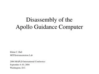
AGC Origins • MIT Instrumentation Lab • Now Charles Stark Draper Laboratory • Early work done on Polaris ballistic missile • NASA contracted MIT to create AGC • Vigorous debate on the interaction of man, spacecraft and computer • As Apollo requirements grew, computer requirement grew even more!
Early Design Issues • What systems will it interface with? • How much computing capacity? • What type of circuit technology? • Reliability and/or in-flight maintenance? • What do we *need* a computer to do? • What does a human interface look like?
AGC Evolution • Origins were with the Polaris SLBM • AGC went through several iterations: • Packaging improvements • Faster logic • Circuitry changed dramatically • Core-transitor logic • “Gate-on-a-chip” (in a “can”) • “Micrologic” two gates on a flat-pack “chip” • More complex instruction set • Increases in memory (both ROM and RAM) • In-flight maintenance requirement dropped
Logic Chips • Fairchild introduced the “Micrologic” chip • Two triple-input NOR gates per chip • Resistor-Transistor Logic • Virtually all logic implemented using the Micrologic chips • Single component greatly simplifies design, testing • Greater production quantities -> better yields and higher quality • Several hundred thousand chips procured (!)
Micrologic chips installed on “Logic Stick”
Logic Assemblies • Subassemblies (sticks) contain 120 chips (240 gates) • Chips welded to multilayer boards • Logic boards essentially identical • Traditional circuit boards could not produce the necessary logic density • Interconnections made through wire-wraps in the underside of the “logic tray”
AGC upper and lower trays Upper tray: Core Rope and Erasable memory Lower tray: Logic and interface modules
AGC Requirements • Autonomously navigate from the Earth to the Moon • Continuously integrate State Vector • Compute navigation fixes using stars, sun and planets • Attitude control via digital autopilot • Lunar landing, ascent, rendezvous • Manually take over Saturn V booster in emergency • Remote updates from the ground • Real-time information display • Multiprogramming • Event timing at centisecond resolution • Multiple user interfaces (“terminals”)
Interfaces (“I/O Devices”) • Gyroscopes and accelerometers • Collectively known as the “IMU” (Inertial Measurement Unit) • Optics • Sextants and telescopes used for navigations sightings • Radars and ranging equipment • 2 radars on LM, VHF ranging on CSM • Engines • CSM: SPS, LM: DPS, APS • Both have 16 attitude control thrusters, CM has additional 12 for reentry • Analog Displays • “8-Balls”, altitude, range, rate displays • Display Keyboards (DSKY’s); 2 in CM, 1 in LM • Abort buttons (!)
AGC Hardware • 36K (16-bit) words ROM (core rope) • 2k (16-bit) words core RAM • Instructions average 12-85 microseconds • 1 cu.ft, 70 pounds, 55 watts • 34 “Normal” instructions • 10 “Involuntary” instructions • 8 I/O instructions
AGC Internal Architecture • Registers • Accumulator, program counter, core bank, return address, etc. • Input/output channels • Data uplink / downlink • No Index register (!) • No serialization instruction! • Interrupt logic and program alarms
Instruction Set • The usual suspects – 11 instructions • “Extended” instructions - 23 • Interpreted instructions • Interpreter “executed” “pseudo instructions” • Called as subroutine library • Trigonometric, matrix, double/triple precision • *Huge* coding efficiency
Instruction Set • 8 I/O – read/write through channels • 10 Involuntary instructions • Example: Update from Inertial Measurement Unit • Counters represent accelerometer and gimbal changes • No context switch! • Currently running program *NOT* interrupted • Counters updated directly by hardware • Processing resumes after involuntary instruction (counter update) finishes • Processing delayed only about 20 microseconds
Memory Architecture • All memory 16 bit words • 14 bits data, 1 bit parity, 1 bit sign for data • Not byte addressable • Read/write memory • Conventional coincident-current core memory • 2K words • Core “Ropes” • Read-only storage • Contained all programming and some data
Memory Architecture • Core “Ropes” • Read-only storage • One “core” reused 24 times for each bit (!) • High storage density • Software “manufactured” into the ropes • Software frozen 10 months before launch! • Ropes installed in spacecraft 3-4 months prior to launch • 6 rope modules, each 6K of memory • Rope modules easily replaced in computer
Addressing memory • Have 8 to 12 bits for addressing • Need to address 36K for instructions, 2K for data • Not enough bits! (need at least 16 bits -> 64k) • Torturous memory bank addressing • Each “bank” was 2K • Special register (SP) specified the particular bank • Lots of extra code needed to manage memory banks
I/O Channels • All 16 bits wide • 7 input channels • 14 output channels • Example of hardware controlled • Engines • Optics • IMU (Guidance platform) • Radars • Analog gauges, some pyrotechnics, a few switches • Display and Keyboard (DSKY)
Man-Machine Interactions • Hasn’t changed in 50+ years • Machine instructions • Opcode - Operands • Command line interface • Command - Options • Even WIMP’s use similar philosophy! • All define an object, and the action to be performed on that object
Using the DSKY interface • DSKY – Display and Keyboard • Specialized keys assigned for each function • Three “registers” displayed data • Commands entered in “Verb-Noun” format • “Verb”: Action to be taken • Display/update data, change program, alter a function • “Noun”: Data that Verbs acts upon • Velocities, angles, times, rates
DSKY Components • Electro luminescent digits • 2 digit displays for Program number, Verb, Noun • 3, 5-digit displays for entering and displaying data, +/- signs • No decimal points! • Keyboard • Warning lights • DSKY separate from computer
Using the DSKY interface • “PRO”: Proceed with the data as offered by computer • “Enter”, “Clear”: – self explanatory • “Key Rel”: Releases control of the DSKY to computer (upon computer request) • “Reset”: resets program alarm
Sample DSKY Query • Programs, Verbs and Nouns referred to by their “number” • Lots to remember: • ~45 Programs, 80 verbs, 90 Nouns • Example: Display time of the next engine burn • Enter Verb, 06, Noun, 33, Enter • Verb 06: Display Decimal Data • Noun 33: Time of Ignition • End with pressing Enter • Notation: V06N33E
Sample DSKY Query: Time of Engine Ignition Verb 06, Noun 33: Display Time of Ignition Verb 06: Display values Program number – P63 Noun 33: Time of Ignition Hours Minutes Seconds . hundredths Time of Ignition: 104:30:10.94 (Mission time)
AGC Executive • Multiprogramming, priority interrupt, real-time operating system • Several jobs running at one time • Up to 7 “long running” jobs • Up to 15 short, time dependent jobs • Only one program has control of the DSKY
Scheduling a New Job • Starting a program requires temporary storage be allocated • Two storage areas available • CORE SET: 12 words • Priority, return address and temp storage • Always required • VAC Area: 44 words • Larger temp storage • Requested usually if vector arithmetic is used • 6 CORE SET’s and 6 VAC areas available
Scheduling a New Job • All work assigned a priority • Executive selects job with highest priority to run • DSKY always the highest priority • In exceptional situations, jobs can change priority • Every 20 milliseconds: • Job queue checked for highest priority tas k • Highest priority job allowed to execute • Jobs are expected to run quickly, and then finish • “Night Watchman” verifies job is not looping and new work is being scheduled (every 1.2 seconds) • Restart forced if a job is hung up
Error Messages • Errors need to be communicated to crew directly • Software might encounter errors or crash • Crew may give computer bad data or task • “Program Alarm” issued, w/error light on • Verb and Noun code indicate type of error • Depending on severity of error, may have to force a computer restart
Error recovery • All programs resister a restart address • Program errors, hung jobs, resource shortages can all force a computer restart • A “restart” is the preferred recovery • NOT the same as rebooting • All critical data is saved, jobs terminated • All engines and thrusters are turned off (most cases) • Hardware is reinitialized • Programs are reentered at their restart point • Process takes only a few seconds
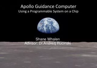
Landing on the moon • One attempt, no second approaches! • AGC handles all guidance and control • Three phases • Braking (Program 63) • Started ~240 nm uprange at 50K feet • Approach (Program 64) • 2-3 nm uprange, begins at ~7K feet • Final Descent (Program 66) • Manual descent, started between 1000 to 500 feet
Lunar Module Descent Profile Braking Phase: Program 63 Approach Phase: Program 64 Terminal Descent: Program 66
Program 63: Begin decending • Started 10-20 minutes before descent • Computes landing site targeting • Started with V37E63E • Response V06N61 • Time to go • Time from ignition • Crossrange distance
P63 Overview • Verb 06, Noun 33: time of Ignition • Hours, minutes, seconds • 104:30:10.94 • Verb 06, Noun 62: Velocity info • Abs(V), Tig, Accum (Delta-V) • Flashing Verb 99: Permission to go • Key PRO! Ignition! • P63 displays Verb 06, Noun 63 • Delta altitude, altitude rate, computed altitude
P63 – Braking phase (pre-ignition) Verb 06, Noun 33: Display Time of Ignition Verb 06: Display values Program number – P63 Noun 33: Time of Ignition Hours Minutes Seconds . hundredths Time of Ignition: 104:30:10.94 (Mission time)
P63 – Braking phase (Confirm Engine Ignition) T-35 Seconds, DSKY Blanks for 5 seconds, at T-5, Flashing Verb 99 displayed Verb 99: Please enable Engine Ignition Program number – P63 Noun 62: Pre-ignition monitor Current Velocity Time to ignition (min, sec) Delta V accumulated 3 seconds until ignition! Press PRO[ceed]
P63 – Braking phase (post-ignition) Verb 06, Noun 63: Monitor braking phase of descent Verb 06: Display values Program number – P63 Noun 63: Descent monitor Radar altitude - computed altitude (not valid yet) Altitude rate Altitude
P63 – Accept landing radar updates Verb 57, Enter Verb 57: Accept Radar Updates Program number – P63 Noun 63: Descent monitor Radar altitude - computed altitude (not valid yet) Altitude rate Altitude
P63 – Landing Radar Accepted Verb 06 automatically redisplayed Verb 06: Display values Program number – P63 Noun 63: Descent monitor Radar altitude minus computed altitude (now valid) Altitude rate Altitude
P63 – Monitoring the descent Antenna angle % Fuel Computer displays were compared against a “cheat sheet” Velcro’d onto the instrument panel Time from Ignition LM Pitch angle