Download
1 / 19
190 likes | 294 Views
Magnets for the phase I LHC upgrade. P. Fessia with the contribution of F. borgnolutti F. Cerutti M. Karppinen R. Ostoijc H. Prin F. Regis E. Todesco D. TomMasini E. wildner and of all the SLHC-IR Upgrade phase I project team and LIUWG team.

E N D
Magnets for the phase I LHC upgrade P. Fessiawith the contribution of F. borgnoluttiF. Cerutti M. KarppinenR. Ostoijc H. Prin F. Regis E. TodescoD. TomMasiniE. wildnerand of all the SLHC-IR Upgrade phase I project team and LIUWG team This project has received funding from the European Community's Seventh Framework Programme (FP7/2007-2013) under the Grant Agreement no212114
Summary Guidelines Heat deposition Insulation Magnetic design: exploring the parameter space Mechanical feasibility study Correctors preliminary study Collaboration and brief planning
Guide-lines for magnet development Tunnel compatibility Cryogenic load Transport Interfaces and interferences Cost reduction: max use of available material SC cable: LHC dipole cables Collar material: Nippon Steel YUS 130 (thickness 3 mm) Yoke material: Cockerill steel (thickness 5.8 mm) Max use of available LHC experience Max use of existing tooling Cold mass diameter Cryostatingsystem Interconnection main tooling
The new inner triplet deposited heat peaksin the coils Recommended limit Q1 Q2a Q2b Q3 Azimuthal distribution at the longitudinal position of the peak, with and without proposed shielding Peak energy deposition in each longitudinal bin, with and without proposed shielding
Full qualification undergoing Intermediate tape 50 and 75 µm thickness, 3 mm wide • Electrical insulation • 10 stacks • Pole winding (inner layer LHC dipole) before and after curing • Mechanical • E-modulus • E-modulus vs. curing pressure • Heat transfer
Magnetic design 1st results : 120 mm aperture • Short sample gradient VS total coil area (no iron)
Examples of 120 mm aperture cross sections I “Normal Grading” cases • CriticalGradient: 147.9 T/m • Field quality: • b6 = -0.06 units • b10 = 0.04 units • Nb turn of cable 01/coil: 18 • Nb turn of cable 02/coil: 17 • Short sample gradient with iron (collar thickness of 37 mm) : 152.1 T/m (~+2.8%) • CriticalGradient: 147.9 T/m • Field quality: • b6 = -0.35 units • b10 = 0.32 units • Nb turn of cable 01/coil: 18 • Nb turn of cable 02/coil: 18 • Sample short gradient with iron (collar thickness of 37 mm) : 152.8 T/m (~+3.2%)
Examples of 120 mm aperture cross sections II “Special Grading” cases • CriticalGradient: 148.8 T/m • Field quality: • b6 = -0.07 units • b10 = 0.03 units • Nb turn of cable 01/coil: 19 • Nb turn of cable 02/coil: 19 • SS Gradient with iron (collar thickness of 37mm) : 152.8 T/m (~+2.6%) • CriticalGradient: 149.5 T/m • Field quality: • b6 = 0.37 units • b10 = -0.77 units • Nb turn of cable 01/coil: 19 • Nb turn of cable 02/coil: 23 • SS Gradient with iron (collar thickness of 37mm) : 152.9 T/m (~+2.3%)
Key position • Coil radial displacement in function of the angular distance between keys α
Deformations • Dδr = δrmag - δrCD
Next steps • Magnetic design • Re-evaluation using parameters of available and selected cable • Further layer jump and heads consideration • Harmonic sensitivity analysis • Mechanical design • Detailed 2D analysis and optimization • Tolerance analysis • 3D mechanical analysis
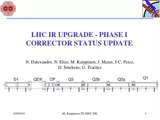
Correctors: ex MQSX RAL results courtesy of James Rochford
A joint R&D and construction effort CEA-Saclay France CIEMAT Spain STFC U.K. CNRS-IN2P3 France EU-FP 7 SLHC-PP program WP6 Integrated project team CERN-CEA-CNRS LHC IR upgrade phase I Special contribution France US collaboration