Download
1 / 36
370 likes | 471 Views
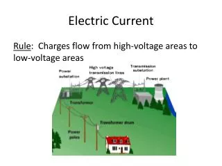
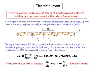
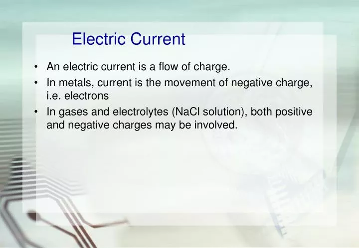
Electric Current. An electric current is a flow of charge. In metals, current is the movement of negative charge, i.e. electrons In gases and electrolytes (NaCl solution), both positive and negative charges may be involved. Electric Current.

E N D
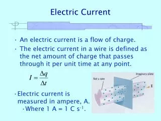
Electric Current • An electric current is a flow of charge. • In metals, current is the movement of negative charge, i.e. electrons • In gases and electrolytes (NaCl solution), both positive and negative charges may be involved.
Electric Current • Current is the rate at which charge is flowing in a circuit. It is the amount of charges that pass through any point of the circuit per unit time. • i.e. I = Q / t • Current is measured in ampere, A, where 1 A = 1 C s-1.
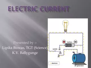
+ – electron flow convention current Conventional current • Scientist first thought that positive charges flow from the positive terminal of a cell to the negative terminal. This is called the conventional current direction. • However, it was found that a current in a metal wire is in fact a flow of negatively-charged electrons in the opposite direction. Nevertheless, the conventional current is still used.
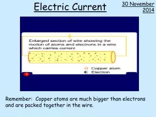
Microscopic view of Electric Current • In a conducting wire, the free electrons are moving about randomly at high speeds, (about 1/1000 of the speed of light) bouncing off the atoms. • Normally, the net flow of charge is zero.
The Mechanism of current flow (1) • If a battery is connected across the ends of a conductor, an electric field is created which causes the electrons to accelerate and gain kinetic energy. • Collisions occur between the accelerating electrons and atoms of the conductor. • As a result, the electrons lose kinetic energy and slow down whilst the ions gain energy. This leads to a temperature rise in the conductor. The electrons are again accelerated and the process is repeated. • The electrons soon reach a steady speed known as their drift velocity.
The Mechanism of current flow • The overall acceleration of the electrons, however, is zero on account of their collisions. They acquire a constant average drift velocity in the direction from the negative to positive of the battery. • Typically value of the average drift velocity is 10-3 m s-1.
Example 1A hair dryer draws a current of 3 A. If it is switched on for 5 minutes, (a) how much charge, and (b) how many electrons have passed through it? • Solution: (a) By I = Q / t 3 = Q / (5 x 60) Q = 900 C (b) charge of 1 electron = 1.6 x 10⁻¹⁹ C no. of electron = 900 / (1.6 x 10⁻¹⁹) = 5.625 x 10²¹
Electromotive Force (e.m.f.) • The electromotive force or e.m.f. of a battery is the energy transferred to unit charge from chemical energy of the battery when the charge passes through the battery. • Unit : volts (V) • The e.m.f. of a battery is 1.5 V if 1.5 J of electrical energy is transferred to each coulomb of charge
or Potential Difference • The potential difference, p.d. or voltage across two points in a circuit is the amount of electrical energy which changes into other forms of energy when unit positive charge passes between these points. • The p.d. across two points in a circuit is 1 V if 1 J of electrical energy is changed into other forms of energy when 1 coulomb of charge passes between these points. 1 V = 1 J C-1.
e.m.f. 4 V 4 J of energy given to each coulomb of charge current 3 J of energy changed into heat and heat and light energy by each coulomb of charge 1 J of energy changed into heat and heat and light energy by each coulomb of charge p.d. 1 V p.d. 3 V
6 V A C B 4 W 2 W Potential at a point • If a convenient point in the circuit is selected as having zero potential, the potentials of all other points can be stated with reference to it. • If current flows from a point A to a point B, then A is regarded as being at a higher potential than • Consider the following circuit p.d. across AB VAB= (1)(4) = 4 V p.d. across BC VBC= (1)(2) = 2 V If VC = 0, VB = and VA = If VA = 0, VB = and VC = 2 V 6 V -4 V -6 V
V V voltage = 3 V voltage = 2.8 V < 3 V closed • A high-resistance voltmeter connected across a cell on open circuit records its e.m.f. E. • If the cell is now connected to an external circuit in the form of a resistor R the voltmeter reading V falls. V is called the terminal p.d. or terminal voltage of the cell. • In our example, the e.m.f. of the cell is 3 V and the terminal voltage is 2.8 V. The difference between the e.m.f. and the terminal voltage is known as the ‘lost’ volt, which is equal to 0.2 V.
‘lost’ volt v e.m.f. r E I terminal voltage V R • The deficiency is due to the cell itself having some resistance. • All power supplies, including the batteries and low voltage power packs, have some resistance due to the way they are made. This is called internal resistance. E = V + v E = IR + Ir For an open circuit, I = 0 ⇒ ‘lost’ volt v = 0. e.m.f. E = terminal voltage V.
‘lost’ volt v e.m.f. r E I terminal voltage V R Example 2Suppose a high-resistance voltmeter reads 1.5 V when connected across a dry battery on open circuit, and 1.2 V when the same battery is supplying a current of 0.3 A through a lamp of. Find (a) the e.m.f., and(b) the internal resistance of the battery. (a) E.m.f = 1.5 V (b) Lost volt = 0.3 V 0.3 = 1.2r r = 0.25 W
Examples relating internal resistance • The typical internal resistance of an E.H.T. is of the order of MW (106W) • To limit the current it supplies and to ensure the safety when using the E.H.T.
Variation of power output with external resistance ‘lost’ volt e.m.f. r E I terminal voltage R Power output to R is a maximum when R = r, internal resistance. I = E / (R + r)
P0 r R What should be the value of R such that maximum power is delivered? • Hence, maximum power is delivered (P0 is maximum) when • R = r. • In this case, the external resistance is matched to the internal resistance and the corresponding power = E2/(4R)
0 R Variation of efficiency with the external resistance 100 % When R is large, h→1 50 % The efficiency equals 50 % when R = r r
Examples of Loads in an Electric Circuit (1) • Loading for greatest power output is common in communication engineering. • For example, the last transistor in a receiver delivers electrical power to the loudspeaker, which speaker converts into mechanical power as sound waves. • To get the loudest sound, the speaker resistance (or impedance) is matched to the internal resistance (or impedance) of the transistor, so that maximum power is delivered to the speaker.
Resistance • The resistance of a conductor is due to the collisions between (1) electrons and the vibrating ions (crystal lattice) and (2) electrons and the defects in crystal lattice at very low temperature. • When the same p.d. is applied across different conductors, different currents flow. Some conductors offer more opposition or resistance to the passage of current than others.
+ – A V – • • Resistance • The resistance R of a conductor is defined as the ratio of the potential difference V across it to the current I flowing through it.
I V 0 Current – p.d. relationships • Ohmic conductor Their I – V graphs are straight lines through the origin. They obey Ohm’s law, which states that the p.d. across a conductor is directly proportional to the current flowing through it, provided that the temperature is constant. Hence, they are called linear or ohmic conductors.
I V 0 Current – p.d. relationships • Filament lamp • The I – V graph bends over as V and I increase, indicating that a given change of V causes a smaller change in I at larger values of V. That is, the resistance of the tungsten wire filament increases as the current raises its temperature and makes it white-hot. In general, the resistance of metals and alloys increases with temperature.
I V 0 Current – p.d. relationships • Semiconductor diode The I – V graph shows that current passes when the p.d. is applied in one direction but is almost zero when it acts in the opposite direction. A diode therefore has a small resistance if the p.d. is applied one way round but a very large resistance when the p.d. is reversed. This one-way property makes it useful as a rectifier for changing alternating current (a.c.) to direct current (d.c.)
I V 0 Current – p.d. relationships • Thermistor The I – V graph bends upwards. This shows that its resistance decreases sharply as its temperature rises.
I V 0 Current – p.d. relationships • Electrolyte The I – V graph shows that there is almost no current flow until the p.d. exceeds a certain value. The phenomenon is due to the existence of a back e.m.f., which the applied p.d. must exceed before the electrolyte conducts.
I V 0 Conclusion: • Ohm’s law as a special case of resistance behaviour. Most of the electronic components are non-ohmic.
Effect of temperature on the resistance of a metal conductor (2) • For metals and a lot of insulators, when temperature is raised, the lattice ions vibrate more vigorously, increasing the frequency of collision between electrons and the lattice. The average drift velocity is reduced and the resistance therefore increases. T ↑⇒ R↑
For semi-conductors, when temperature is raised, greater vibration of atoms breaks bonds, freeing more charge carries (such as electrons) and thereby producing a marked decreased of resistance. • T ↑ ⇒ R↑
The resistance of a conductor depends on its length and thickness. • Notice that the electrons seem to be moving at the same speed in each one but there are many more electrons in the larger wire. • This results in a larger current which leads us to say that the resistance is less in a wire with a larger cross sectional area. It can be shown that R1/A.
Resistance in a Conductor (2) • The length of a conductor is similar to the length of a hallway. A shorter hallway would allow people to move through at a higher rate than a longer one. • So a shorter conductor would allow electrons to move through at a higher rate than a longer one too. • It can be shown that R l .
Resistivity of a material is called the resistivity of the material. The unit of is m.
Example 3Find the resistance of a copper wire if its length and diameter are 5 m and 2 mm respectively. Solution: R = rl/A For the copper wire, r = 1.7 x 10⁻⁸ l = 5 m A = pr2 = p(0.002)2 = 1.2566 x10⁻⁵ m2 R = 1.7 x 10-8x 5 / (1.2566 x10⁻⁵) = 6.76 x 10⁻³W
Power and heating effect • The power of a device is the rate at which it transfers energy.