Download
1 / 203
2.03k likes | 2.04k Views
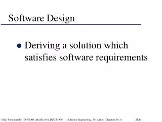
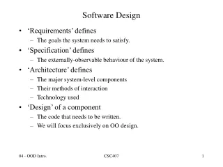
Software Design. During the software design phase, the design document is produced, based on the customer requirements as documented in the SRS document. The activities carried out during the design phase (called as design process) transform the SRS document into the design document.

E N D
Software Design • During the software design phase, the design document is produced, based on the customer requirements as documented in the SRS document. • The activities carried out during the design phase (called as design process) transform the SRS document into the design document.
Classification of Design Activities • Classified into two important stages. • 1. Preliminary (or high-level) design and • 2. Detailed design. • High-level design, a problem is decomposed into a set of modules. • Detailed design each module is examined carefully to design its data structures and the algorithms
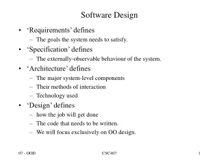
Charact. of good S/w design • Correctness: mean to make right what is wrong. Correct refers to eliminating faults, errors, or defects: I corrected the spelling mistakes. • Understandability: readers can easily understandable. If it is plain language • Efficiency: quality of work should be necessary( avoid the wasteful usages) • Maintainability: Software must evolve to meet changing needs
Complex design leads the cost of SDLC. Two approaches: • Modularity • Layered 1). use consistent and meaningful names 2). should follow the principle of decomposition and abstraction.
Modularity • Modularity is a fundamental attributes of any good design. • Decomposition of a problem cleanly into modules: 1. divide and conquer principle. 2. Modules are almost independent of each other
Cont… If modules are independent: • modules can be understood separately. • reduces the complexity.
Cont… In technical terms, modules should display: 1. high cohesion 2. low coupling.
Layered Design • Graphical representation of call relations and form hierarchy of layers. • Lower layer is unaware of the higher layer module.
LAYERED ARRANGEMENT OF MODULES M1 M1 Layer 0 --------------------------------------------------------- M2 M3 M2 M3 Layer 1 --------------------------------------------------------- M4 M5 M6 M4 M5 M6 Layer 2 Layered design with good Control abstraction Layered design showing poor Control abstraction
Cohesion And Coupling • Good system design: System decomposed into modules. • Good decomposition: high cohesion and low coupling. • Cohesion is a measure of the Functional strength of a module. • Coupling is a measure of the degree of interaction between two modules.
Cohesion Cont… Less cohesion often correlates with high coupling and vice-versa. How? • high cohesive: Modules cooperate with each other for performing single objective. • Functional independency(highly cohesive and low coupling): error isolation, understandability and scope of reuse.
Classification of cohesiveness Classes of cohesion: Low High
Cohesion cont… 1. Coincidental Cohesion: • A module performs set of tasks that relate to each other very loosely. • Random collection of functions.
Cohesion cont… 2. Functional cohesion: If different functions cooperate to complete a single task. Example: • Module Name: Manage-Book-Lending • Function: issue-book, return-book, Find-borrower.
Cohesion cont… 3. Logical Cohesion: • All elements of the module perform similar operations such as data input, data output, etc. • Example: various types of reports(time table).
Cohesion cont… 4. Temporal Cohesion: • Functions of the module are executed in the same time span. • Example: Booting of the system.
5. Procedural Cohesion: • Set of functions of the module are executing one after the other. Example: Place an order. login -> place_order-> check_order ->Print_order-> Print_bill->logout.
6. communicational Cohesion: • Functions refer to or update the same data structure. • Example: module: student • Functions: admit_student, enter_marks.
7. Sequential Cohesion: • Different functions of the module execute in a sequence, and output from one function is input to the next in sequence. • Example: Attendance module • Enter list/ retrieve list • Mark attendance • View attendance
Examples of Cohesion-1 Function A Function A Function A’ Function A’’ Time t0 Time t0 + X Time t0 + 2X Function B Function C logic Function D Function E Coincidental Parts unrelated Logical Similar functions Temporal Related by time Function A Function B Function C Procedural Related by order of functions
Examples of Cohesion-2 Function A Function B Function C Function A Function B Function C Communicational Access same data Sequential Output of one is input to another Function A part 1 Function A part 2 Function A part 3 Functional Sequential with complete, related functions
Range of Coupling High Coupling Content Common Control Stamp Data Loose Low
Data Coupling • Definition: The dependency between module A and B is said to be data coupled if their dependency is based on the fact they communicate by only passing of data. • Example: call by value and call by reference.
Stamp Coupling • Definition: Stamp coupling occurs between module A and B when complete data structure is passed from one module to another • Example: in C and in PASCAL • Data is passed between the modules.
The print routine of the customer billing accepts a customer data structure as an argument, parses it, and prints the name, address, and billing information. Example-1 Module: Customer billing
Control Coupling • Definition: Two modules exhibit control coupling if one (``module A'') passes to the other (``module B'') a piece of information that is intended to control the internal logic of the other. • Example: This will often be like, if-then statement, or while loop
Common Coupling Definition: With common coupling, module A and module B have shared data. Global data areas are commonly found in programming languages.
Software Design Fig. 8 : Example of common coupling
Data manager component is responsible for data in data store. Processes send data to and request data from data manager Example-1 Process control component maintains current data about state of operation. Gets data from multiple sources. Supplies data to multiple sinks.
Content coupling • Definition: One component references contents of another. • Example: • Mostly in low level languages. • Branch into another branch. • Component modifies another’s code, e.g., jumps into the middle of a routine
Software Design Fig. 9 : Example of content coupling
Part of program handles lookup for customer. When customer not found, component adds customer by directly modifying the contents of the data structure containing customer data. When customer not found, component calls the AddCustomer() method that is responsible for maintaining customer data. Example of Content Coupling-1
High coupling leads to complexity and difficulty in the design ?
Coupling: Degree of dependence among components Loosely coupled-some dependencies No dependencies Highly coupled-many dependencies
Function oriented design approach • It is a mature technology • Top-down decomposition • Black-box view • Provides certain services • Services are known as high-level functions
Example: function: create_new_library_member • Subfuctions: • Assign_membership_number • Create_member_record • Print_bill • Can be split into more detailed functions
Centralized system state • System state can be defined as: • The values of certain data items that determine the response of the system to a user action or an external event. • Such data have global scope. • Example: set of books in library automation system
Example: • Create_new_member • Delete_member • Update_member_record • All share data such as member_records.
Design approaches for function oriented design • Structured design by Constantine and Yourdan [1979] • Jackson’s structured design by Jackson [1975] • Warnier_orr methodology [1977, 1981] • Step-wise refinement by Wirth [1971] • Hatley and Pirbhai’s methodology [1987]
Chapter 6 FUNCTION – ORIENTED SOFTWARE DESIGN Presented By Pooja Devi Assistant Professor Lovely Professional University
Data flow diagram and structure chart Design Tech. : SA/SD
Overview of SA/SD Methodology • Consists of two distinct activities called transformers. • During structured analysis: • functional decomposition takes place. • During structured design: • mapped to a module structure.
Structured Analysis • The results of structured analysis can be easily understood and reviewed even by ordinary customers: • Based on principles of: • Top-down decomposition approach. • Divide and conquer principle:
Data Flow Diagram(DFD) • DFD is a hierarchical graphical model: • shows the different functions (processes) of the system and • data interchange among the processes. • Applicable to other areas also: • e.g. for showing the flow of documents or items in an organization,
Data Flow Diagrams (DFDs) • A DFD model: • uses limited types of symbols. • simple set of rules • easy to understand: • it is a hierarchical model.
Data Flow Diagrams (DFDs) • Primitive Symbols Used for Constructing DFDs:
External Entity Symbol • Represented by a rectangle • External entities are real physical entities: • input data to the system or • consume data produced by the system. • Sometimes external entities are called terminator, source, or sink, external h/w & s/w. Librarian
Function Symbol • A function such as “search-book” is represented using a circle: • This symbol is called a processor bubbleor transform. • Bubbles are annotated with corresponding function names. search-book