Download
1 / 54
551 likes | 690 Views
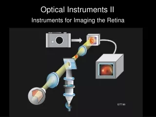
Learn about the principles behind telescopes and microscopes, including magnification, lenses, and image formation. Explore how different optical instruments work and their applications in ophthalmology. Discover the basics of angular and microscope magnification.

E N D
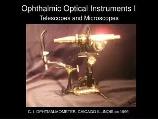
Ophthalmic Optical Instruments I Telescopes and Microscopes C. I. OPHTMALMOMETER, CHICAGO ILLINOIS ca 1899
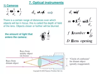
fo M = - fe Astronomical (Keplerian) Telescope Image is Inverted objective eyepiece Fo Fe fe fo Virtual image at 25 cm
D Astronomical Telescope objective eyepiece Fe Fo fe fo Virtual image at infinity
plus lens fp fp negative lens Galilean Telescope fp fp’s coincide final telescope parallel rays
Viewing Through a Galilean Telescope parallel iImage rays object emmetropic eye UPRIGHT OBJECT APPEARS UPRIGHT D GTT 04
ANGULAR MAGNIFICATION Apparent size of object depends on angle it subtends at eye.
ANGULAR MAGNIFICATION On average, an object cannot be closer than 25 cm from the eye to be seen clearly. Average distance of most distinct vision
cm (cm)
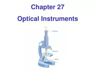
BASIC MICROSCOPE magnifier real image magnification
MICROSCOPE MAGNIFICATION 25 = M f 2 Im 25 Im = M = M X Ob Ob 1 f total
OBJECTIVES n a Numerical Aperture (NA) Light gathering ability Resolution a NA = sin n EXAMPLE a = 14 D n = 1.00 (air) w.d. NA = 1.00 x sin(14 ) NA = 0.24
OBJECTIVES N.A. Examples
D EYEPIECES (OCULARS) Huygens Ramsden parallel rays from eyepiece Real image Real image converging rays from objective
EXPERIMENT 4 Basic Microscope iris diaphragm real image on card onion skin f Produce real image of onion skin on card. Mark distance of real image on base.
EXPERIMENT 4--CONTINUED View real image with magnifier (“eyepiece”) real image plane f Adjust iris diaphragm. How does image change? 25 Im What is the total magnification? = M X Ob f total
The slit-lamp biomicroscope begins with a microscope…. Eyepiece Objective Specimen
….turned on its side ….change specimen, objective & eyepiece Huygens eyepiece objective subject image plane …….fundamental slit-lamp biomicroscope
Build in magnification change without changing working distance working distance fobj Galilean telescope to change mag no image in image plane
D Build in magnification change without changing working distance working distance fobj Galilean telescope to change mag no image in image plane
D …..add lens to form image in eyepiece image plane astronomical telescope
2 right-angle prisms 1800 image rotation displace image horizontally reduce length of telescope Porro* prism Porro -Abbe *Ignazio Porro. 1801 – 1875. Italian optical instrument maker
D Slit-lamp with folded optical path
Operating microscope optics are very similar to those of the slit-lamp.
binocular astronomical telescopes Change magnification without changing working distance magnification change: Galilean telescopes prism objective lens
Useful in seeing corneal endothelial cells Endothelial cells posterior surfaces flat & adjacent to aqueous Difference in index of refraction gives specular reflection Specular Microscope specular == “mirror-like”
D Specular Microscope halogen lamp condenser slit dipping cone lens M objective film or CCD Ramsden eyepiece
endothelium { slit image specular reflections and stray light
Confocal Principle Red cell in thick sample imaged by lens Pinhole in image plane passes all light from blue cell Blue cell, nearer to surface, imaged at different point Pinhole blocks most of light from red cell Based on Webb, RH, Rep Prog Phys 59:427
Confocal Principle Point source CONFOCAL with blue cell & pinhole selectively illuminates blue cell Confocal point source gives less light to red cell, and most is blocked by pinhole Beam splitter makes confocal microscope epitaxial Based on Webb, RH, Rep Prog Phys 59:427
Confocal Optical Systems: Pinhole allows light from small volume in sample. Other stray light blocked. Confocal point source confines light to small volume in sample. Rejects stray light Allows Z-axis “sectioning”
Confocal systems can improve imaging Standard specular microscope Confocal specular microscope
CCD camera M lamp M confocal slit slit rotating mirror Koester’s Confocal scanning microscope objective specimen
Tandem Scanning Confocal Microscope Scanned (laser) Spot Confocal Microscope Scanned Slit Confocal Microscope Other Scanning Methods and Confocal Microscopes
Uses Nipkow disk Paul Nipkow (1860 -1940) Studied with Helmholtz Invented disk in 1883 Used for telegraphing pictures Later used in 1st television r q Sets of holes in plate Holes on Archimedes spirals r = a + bq D Tandem Scanning Confocal Microscope
Very light inefficient Petran Tandem Confocal Scanning Microscope


![OPHTHALMIC SURGERY INSTRUMENTS [SURGICOSE]](https://cdn4.slideserve.com/8061795/medical-instruments-medical-instruments-dt.jpg)