Download
1 / 15
150 likes | 299 Views
IBIC analysis of gallium arsenide Schottky diodes C.Manfredotti 1,2 , E.Vittone 1,2 ,F.Fizzotti 1,2 , A.LoGiudice 1,2 , F.Nava 3 1 Dip. Fisica Sperim., Università di Torino, INFN-Sez. di Torino, via P.Giuria 1, 10125 Torino (I)

E N D
IBIC analysis of gallium arsenide Schottky diodes C.Manfredotti1,2, E.Vittone1,2,F.Fizzotti1,2, A.LoGiudice1,2, F.Nava3 1Dip. Fisica Sperim., Università di Torino, INFN-Sez. di Torino, via P.Giuria 1, 10125 Torino (I) 2INFM- Unità di Torino Università, via P.Giuria 1, 10125 Torino (I) 3 Dip. di Fisica, Universitá di Modena, Via Campi 213/A, 41100 Modena, Italy
Summary • IBIC ( ION BEAM INDUCED CHARGE ) PRESENTED AS A POWERFUL METHOD IN ORDER TO INVESTIGATE ELECTRICAL FIELD DEPTH PROFILE AND ELECTRICAL HOMOGENEITY OF DEVICES • FRONTAL IBICC : RESULTS ON ELECTRICAL HOMOGENEITY OF CARBON DOPED n- TYPE SAMPLES • LATERAL IBICC : ANALYSIS OF RESULTS OBTAINED FROM A STANDARD SI SAMPLE IN COMPARISON WITH THEORETICAL MODELS
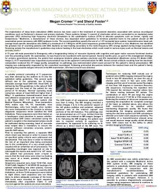
2 mm 1 cm (frontal irradiation) 2 MeV proton microbeam pre-amplifier Schottky contact GaAs m lateral IBIC m 1 . 2.4 MeV proton microbeam active region 0 sample holder ohmic contact (back irradiation) 2 MeV proton microbeam
IBIC Set up Ion beam frontal lateral
FRONTAL IBIC • 2 MeV protons ( range in SiC 34 mm ) • microbeam diameter 2 mm • scan area up to 2 x 2 mm2 • event-by-event data collection mode • “ historical “ check of possible effects of radiation damage
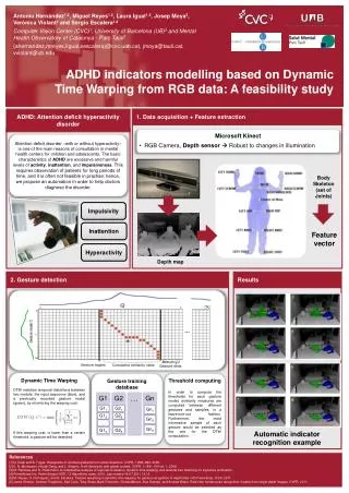
Effect of carbon doping on charge collection efficiency uniformity Frontal IBIC GaAs carbon doping effects ( Freiberger ): - lowering of dark current - compensation of EL2 traps ( ? ) - lowering of charge collection efficiency 2 samples L12 C conc. 3 1014 cm-3 A15 C conc. 8 1014 cm-3
FRBBL12 C = 3x1014 cm-3
FRBAn15 C = 8x1014 cm-3
LATERAL IBIC • 2 MeV protons • polished cross section surfaces • no surface effect : penetration depth 34 mm and 2/3 of energy released at the end of the range ( Bragg’s peak ) • the electric field keeps apart the generated carriers : no plasma recombination • charge collection efficiency values ( cce ) are obtained by comparison with a Si surface barrier detector • cce profiles may be obtained from different regions of the scanned area by averaging over different rows or columns • by fitting data by using an equation for cce obtained on the basis of Ramo’s theorem ) it is possible to check with different possible electrical field profiles
LATERAL IBICC 2.4 MeV protons
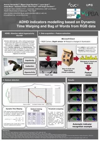
IBICC collection efficiency profiles 200 m ) m 100 90 Depletion width ( 80 70 60 Slope 0.89 50 40 30 20 20 20 30 40 50 60 70 80 90 100 100 200 Bias voltage ( V )
te=1.4 ns te=1.3 ns W=65 mm te=1.5 ns te=1.5 ns W=65 mm te=1.3 ns te=1.3 ns W=45 mm te=1.8 ns te=1.5 ns W=47 mm
CONCLUSIONS Frontal IBIC: Compensation with C : • increases the homogeneity of the response, • worsens energy resolution, but • lowers the charge collection efficiency.
CONCLUSIONS Lateral IBIC • Results are in perfect agreement with the model based on electrical field activated compensation of donors by EL2 centers • The depletion layer width increases almost linearly with bias voltage. • Different kinds of approximation of electrical field profile give very similar results concerning electron and hole lifetimes, but different depletion layer widths. • It may not be appropriate to use Hecht’s relationship in order to interpret the results, because in the presence of space charge Ramo’s theorem is no more valid: the extended Ramo’s theorem or better Gunn’s principle are needed.