Download
1 / 29
290 likes | 492 Views
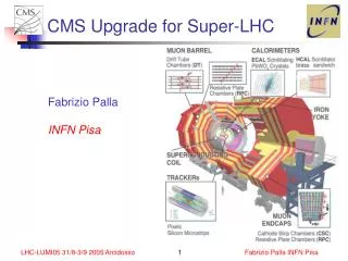
ARES Upgrade for Super KEKB. KAGEYAMA Tatsuya for the KEKB RF ARES cavity group Introduction Fundamental mode issues HOM load issues Input Coupler R&D Summary. 2CA-2: T. Kageyama et al., “The Growth Potential of the ARES Cavity System toward Super-KEKBâ€, SAST’03

E N D
ARES Upgrade for Super KEKB KAGEYAMA Tatsuya for the KEKB RF ARES cavity group • Introduction • Fundamental mode issues • HOM load issues • Input Coupler R&D • Summary 2CA-2: T. Kageyama et al., “The Growth Potential of the ARES Cavity System toward Super-KEKB”, SAST’03 1P-071: 阿部哲郎、他『高周波入力結合器におけるマルチパクタリングの研究』、SAST’03 1P-074: 竹内保直、他『炭化珪素セラミックスの誘電特性とHOM減衰器設計への応用』、SAST’03 KAGEYAMA, T. Super-KEKB WS Nov. 28, 2003
Accelerator Resonantlycoupled with Energy StorageARES3-cavity system stabilized with the π/2-mode operation KAGEYAMA, T. Super-KEKB WS Nov. 28, 2003
Fundamentals of the ARES cavity system Operation of a conventional copper cavity under the heavy beam loading (2.6A for KEKB LER) would bring on The longitudinal CBI (Coupled-Bunch Instability, µ = -1, -2, • • • ) driven by the accelerating mode, which is to be detuned downward from the fRF by ∆fawhere |dfa| would amount to ~2Xfrev . cf. frev = 99kHz for KEKB KAGEYAMA, T. Super-KEKB WS Nov. 28, 2003
Fundamentals of the ARES cavity systemcont’d S-cav functions as a kind of EM flywheel. A flywheel is a device for storing energy or momentum in a rotating mass, used to minimize variations in angular velocity and revolutions per minute, as in a machine subject to fluctuation in drive and load. How to couple A-cav with S-cav is the most important issue. C-cav engaged to stabilize the coupled cavity system with the π/2-mode operation and also suppress CBI due to the parasitic modes. KAGEYAMA, T. Super-KEKB WS Nov. 28, 2003
Fundamentals of the ARES cavity systemcont’d QC-cav ≈ 50 for p/2 mode KAGEYAMA, T. Super-KEKB WS Nov. 28, 2003
Fundamentals of the ARES cavity systemcont’d • The stored-energy ratio of the π/2 mode: • The EM field distribution of the π/2 mode is stable against detuning of A-cav (= ∆fa) loaded with the beam. • The amount of detuning of A-cav can be reduced as: • The parasitic 0 and π modes can be selectively damped (QL ≈ 100) with an antenna-type coupler attached to C-cav. • Furthermore, the damped 0 and π modes are located almost symmetrically with respect to the π/2 mode. Therefore, their impedance contributions to CBI can be counterbalanced. • C-cav functions as a filter to isolate S-cav from A-cav’s HOMs. KAGEYAMA, T. Super-KEKB WS Nov. 28, 2003
ARES Operation Status in KEKB RF Parameters of the π/2 mode: Us / Ua = 9 R / Q = 15 Ω Q0 = 1.1 x 10⁵ Pc = 150 kW / cav Vc = 0.5 MV /cav LER (e+): 20 ARES cavities • Total Vc = 8 MV (0.4MV/cav) • Beam current (max.): ~1.8A • Input RF power/cav: ~300kW • HOM power/cav: ~5kW • Trip rate: ~1/cav/3months According to stats for Apr.~Jun., 2003 HER (e-): 12 ARESs and 8 SCCs • Total Vc = 15 MV = 3.84MV(ARES) + 11.16 (SCC) • Beam current (max.): ~1.1A KAGEYAMA, T. Super-KEKB WS Nov. 28, 2003 ARES cavities in the LER RF section Fuji D7
ARES Upgrade for Super-KEKB LER: 2.6 A by 20 ARESs HER: 1.1 A by 12 ARESs + 8 SCCs LER: 9.4 A by 28 ARESs HER: 4.1 A by 16 ARESs + 12 SCCs We are planning to remodel the accelerating cavity part and the HOM loads for Super-KEKB LER. WG HOM Load GBP HOM Load Coupling Slot Width: 120 mm Height: 160 mm KAGEYAMA, T. Super-KEKB WS Nov. 28, 2003
ARES Upgrade for Super-KEKBFundamental mode issues 2.6 A by 20 ARESs for LER ∆fa = -200 kHz 9.4 A by 28 ARESs for LER ∆fa = -710 kHz • CBI driven by the π/2 accelerating mode: We need to increase the stored-energy ratio Us / Ua. ∆fπ/2 = 71 kHz if Us / Ua = 9 unchanged. (cf. frev= 99 kHz) • CBI due to the parasitic 0 and π modes: We have investigated the impedance imbalance caused by larger detuning of A-cav. KAGEYAMA, T. Super-KEKB WS Nov. 28, 2003
CBI due to the π/2 mode Table 1: RF parameters of ARES cavity for Super KEKB LER. Us /Ua 9 15 18 Coupling Slot 120 ´ 160120 ´ 175 120 ´ 182W´H mm2 I9.4 (2.6) A # of Cavities 28 (20) fRF 508.887 MHz h 5120 Vc 0.5 MV Q0 1.11 1.27 1.32 R/Q input Pc kW f kHz Numbers in ( ) for KEKB LER KAGEYAMA, T. Super-KEKB WS Nov. 28, 2003
CBI due to the π/2 mode (cont’d) Growth rates of the CBIs (µ = -1, -2, -3) due to the π/2 mode, plotted as a function of Us / Ua . Coupling Impedance of the π/2 mode loaded with 9.4 A for Us / Ua = 9, 15, 18. By increasing Us / Uafrom 9 to 15, the growth rate of the severest CBI (µ = -1) can be reduced by one order of magnitude and down to t = 1.5 ms, where some RF feedback system could manage to damp it. KAGEYAMA, T. Super-KEKB WS Nov. 28, 2003 S. Yoshimoto et al., “The -1 mode damping system for KEKB”, in this conference
CBI due to the 0 and π modes The damped 0 and π modes (Ua:Uc = 1:1 when fa = 0 kHz) are located almost symmetrically with respect to the π/2 mode ( ≈ fRF ). For KEKB (fa = -200 kHz), Re[Z//] has a small asymmetry with respect to fRF. |R+ - R-|max ~500 Ω/ARES → t ~46 ms cf. trad ~23 ms (KEKB) The EM field distributions (Ua:Uc) of the 0 and π modes are subject to the perturbation of order of fa / (fπ - f0). fa = -200 kHz (KEKB) → -710 kHz (Super-KEKB) The delicate counterbalancing may be deteriorated in Super-KEKB. KAGEYAMA, T. Super-KEKB WS Nov. 28, 2003
CBI due to the 0 and π modes (cont’d) Top: Re[Z//] of the 0 and π modes Bottom: Re[Z//] imbalance R+ - R- with respect to fRF. • The CBI due to the 0 and π modes: t = 3.3 ms for Us / Ua = 9 (9.4 A) cf. t = 46 ms for Us / Ua = 9 (2.6 A KEKB) t = 4.0 ms for Us / Ua = 15 (9.4 A) to be damped by longitudinal FB kickers the first order term fa / (fπ - f0) where fπ - f0 ∝ ka ∝ (Us / Ua)1/2 KAGEYAMA, T. Super-KEKB WS Nov. 28, 2003
ARES upgrade for Super-KEKBHOM load issues HOM-damped structure for ARES • Based on the conceptual demonstrator ARES96 • Carefully designed to be smoothly embedded into the whole ARES scheme • Consists of 4 HOM WGs and 2 GBPs (Grooved Beam Pipe) HOM WG: Monopole & Dipole(V) HOMs GBP: Dipole(H) HOMs KAGEYAMA, T. Super-KEKB WS Nov. 28, 2003
WG HOM load (KEKB) WG HOM load: • Two bullet-shape SiC absorbers at the end of the HOM WG. • Each absorber directly water-cooled. • Power capability tested up to 3.3 kW / bullet (26 kW / cavity). KAGEYAMA, T. Super-KEKB WS Nov. 28, 2003
GBP HOM load (KEKB) GBP HOM load: • 8 SiC tiles per groove, brazed to a water-cooled OFC plate. • Power capability tested up to 0.5 kW / groove (2 kW / cavity). KAGEYAMA, T. Super-KEKB WS Nov. 28, 2003
HOM load status in KEKB WG and GBP HOM powers per cavity measured in the KEKB LER, compared with theoretical predictions (sz = 7 mm). Loss factors computed for the whole damped structure (3D) and the GBPs (3D), together with those for a simplified axially symmetric structure (2D) with circular beam pipes (CBPs). KAGEYAMA, T. Super-KEKB WS Nov. 28, 2003
Prospect of HOM power for Super-KEKB WG HOM: ~80 kW / cavity GBP HOM: ~20 kW / cavity Super-KEKB LER: 9.4 A, ~5000 bunches, sz = 3mm. Extrapolation HOM data taken in KEKB LER: 1224 bunches, sz = 7mm. cf. KEKB LER design: 2.6 A, ~5000 bunches, sz = 4mm KAGEYAMA, T. Super-KEKB WS Nov. 28, 2003
Upgrading WG HOM load for Super-KEKB WG HOM load for Super-KEKB LER: ~80 kW / cavity • HPT’d up to 26 kW/cavity (3.3 kW/bullet) for KEKB: The limit due to the maximum RF power stably supplied by the current L-band klystron. • Perform HPT over 3.3 kW/bullet: Resume HOM load test bench, hopefully with a new klystron supplying more than 10 kW. • Increase # of absorbers per WG. KAGEYAMA, T. Super-KEKB WS Nov. 28, 2003
Upgrading GBP HOM load for Super-KEKB GBP HOM load for Super-KEKB LER: ~20 kW / cavity • HPT’d up to 2 kW/cavity (0.5 kW/groove) for KEKB. • Need to upgrade the power capability by one order of magnitude. A new design with directly water-cooled SiC absorbers. ? KAGEYAMA, T. Super-KEKB WS Nov. 28, 2003
GBP evolves into Winged Chamber Y.Suetsugu et al., “Development of Winged HOM Damper for Movable Mask in KEKB”, Proc. PAC2003. SiC Beam Chamber Slot Winged chamber loaded with directly water-cooled SiC bullets: • Developed under collaboration between the KEKB vacuum and ARES cavity groups. • Used in the movable mask sections in KEKB since 2002. • Perform HPT over 5 kW / bullet. KAGEYAMA, T. Super-KEKB WS Nov. 28, 2003
Input Coupler Upgrade Monitor port for arc detection Over- and under-cut structure for impedance matching Coaxial line WX77D multipactoring discharge problem Ceramic RF window Door-knob transformer from rectangular WG to coaxial line Coupling loop ICF-203 flange Monitor port for arc detection Capacitive iris RF power ( = Pc + Pbeam ) ~400kW for KEKB ~800kW for Super-KEKB KAGEYAMA, T. Super-KEKB WS Nov. 28, 2003
Input Coupler Upgrade (cont’d) S-cav (TE013 mode) Multipactoring-free RF power p/2-mode terminator RF power Dummy load HPT setup (old) RF power < 1 MW HPT setup (new) RF power < 500 kW KAGEYAMA, T. Super-KEKB WS Nov. 28, 2003
Input Coupler Upgrade (cont’d) HPT setup KAGEYAMA, T. Super-KEKB WS Nov. 28, 2003
Input Coupler Upgrade (cont’d) KAGEYAMA, T. Super-KEKB WS Nov. 28, 2003 SAST’03 1P-071: 阿部哲郎『高周波入力結合器におけるマルチパクタリングの研究』
Input Coupler Upgrade (cont’d) DT of the cooling water for the outer conductor TV camera Single-surface MP @ the WX77D outer conductor RF input power: 160~180kW KAGEYAMA, T. Super-KEKB WS Nov. 28, 2003 SAST’03 1P-071: 阿部哲郎『高周波入力結合器におけるマルチパクタリングの研究』
Input Coupler Upgrade (cont’d) RF power Dummy load HPT setup (future) RF power up to ~1 MW KAGEYAMA, T. Super-KEKB WS Nov. 28, 2003
Summary • By increasing Us/Ua from 9 to 15, the severest CBI (µ = -1) due to the π/2 accelerating mode can be eased by one order of magnitude and down to t = 1.5 ms (Super-KEKB LER) where some RF feedback system could manage to damp it. • The growth time of the CBI due to the impedance imbalance between the 0 and π modes has been estimated as t = 4 ms (Super-KEKB LER). Some longitudinal FB kicker system will be needed. • For Super-KEKB LER, we need to upgrade the power capabilities of the WG and GBP HOM loads to ~80kW and ~20kW per cavity, respectively. The GBP with indirectly water-cooled SiC tiles may evolve into a winged chamber loaded with directly water-cooled SiC bullets. • R&D of the input coupler for Super KEKB is being carried out with a new HPT setup using an S-cav. First, single-surface MP discharge on the outer conductor of the coaxial line section (WX77D) should be suppressed. • We should first resume HPT for the HOM loads, hopefully with an L-band klystron supplying more than 10kW. KAGEYAMA, T. Super-KEKB WS Nov. 28, 2003
And that’s all? KAGEYAMA, T. Super-KEKB WS Nov. 28, 2003