Download
1 / 26
280 likes | 614 Views
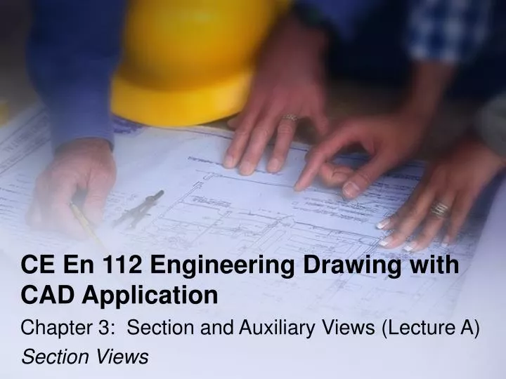
CE En 112 Engineering Drawing with CAD Application. Chapter 3: Section and Auxiliary Views (Lecture A) Section Views. Lecture Outline. Sectioning basics (3.1, p.132) Cutting plane lines (3.2, p.136) Section line practices (3.3, p.136) Section view types (3.4, p.138)

E N D
CE En 112 Engineering Drawing with CAD Application Chapter 3: Section and Auxiliary Views (Lecture A) Section Views
Lecture Outline • Sectioning basics (3.1, p.132) • Cutting plane lines (3.2, p.136) • Section line practices (3.3, p.136) • Section view types (3.4, p.138) • Special sectioning conventions • Next class
Objectives • Apply the concept of cutting planes to create section views • Represent cutting plane lines and section lines, using conventional practices • Create full, half, offset, removed, revolved, broken-out and assembly section views using conventional practices • Create conventional breaks for different materials and cross sections • Represent ribs, webs, and thin features in section, using conventional practices • Represent aligned sectioned features, using conventional practices
Sectioning Basics (3.1) • Section view: An important aspect of design and documentation used to improve clarity and reveal interior features of parts and structures – also used to reduce the number of hidden lines in a drawing
Sectioning Basics (con’t) • Sectional drawings: Multiview technical drawings that contain special views of a part or parts—views that reveal interior features—using a minimum number of hidden lines
Sectioning Basics (con’t) • Traditional section views are created by passing an imaginary cutting plane through the object parallel to one of the primary multiview planes
Sectioning Basics (con’t) • Hidden lines are minimized as the section view reveals hidden features without the use of hidden lines
Edges that can be seen in section view need to be drawn as visible (solid) lines Sectioning Basics (con’t)
Cutting plane lines: Show where the cutting plane passes through the object representing the edge view of the cutting plane adjacent to section view Cutting Plane Lines (3.2) Pay special attention to the direction of the arrows
Cutting Plane Lines (con’t) • Thick (0.6 mm or 0.032 inch) dashed lines that extend past the edge of the object ¼” or 6 mm with line segments at each end drawn at 90 degrees and terminated with arrows • The arrows represent the direction of the line of sight and point away from the sectioned view • Two line types are acceptable for cutting planes
Section lines (cross-hatch lines): Added to indicate the surfaces that are cut by the imaginary cutting plane Different symbols are used to represent various materials With so many different materials the general symbol (cast iron) is used in most instances Section Line Practices (3.3)
General purpose line is drawn at 45-degrees spaced 1/16 to ⅛ inch (1.5 mm to 3 mm) depending on drawing size Section lines should not run parallel or perpendicular to the visible outline Section Line Practices (con’t)
Section Line Practices (con’t) • Avoid placing dimensions or notes within the lined areas – if they must be placed there, omit the section line in the area of the note
If an area is too large use outline sectioning Thin parts in section are represented without section lines Section Line Practices (con’t)
Special Sectioning Conventions • Conventional practices have been established to handle section views of special situations including holes, ribs, webs, and other thin features • These are not in the text, however, a brief explanation will be included in the following slides
Special Conventions (con’t) Thin features, such as webs, are left unsectioned when cut parallel to the feature by the cutting plane
Special Conventions (con’t) Thin features are section lined with alternate lines if it clarifies the geometry of the object
Special Conventions (con’t) Web When the feature is not lost, section lines are omitted
Special Conventions (con’t) Aligned section conversions are used to rotate the holes into position along the vertical center line
Special Conventions (con’t) Aligning spokes in section views is the conventional method of representation
Conventional breaks: Used for revolved section views or for shortening the view of an elongated part Special Conventions (con’t) View shortened
Next Class • How to create auxiliary views • MD HW#3 is due • MD HW#4 is assigned