Download
1 / 62
620 likes | 763 Views
Wireless Communications. Instructor: Fatima Naseem Computer Engineering Department, University of Engineering and Technology, Taxila. Contact. Fatima Naseem Room # 17, CED. fatima@uettaxila.edu.pk Student meeting time: Monday 8:00 am to 11:00 am. Course Books.

E N D
Wireless Communications Instructor: Fatima Naseem Computer Engineering Department, University of Engineering and Technology, Taxila
Contact • Fatima Naseem Room # 17, CED. fatima@uettaxila.edu.pk • Student meeting time: Monday 8:00 am to 11:00 am
Course Books • “Wireless Communications and Networks” by William Stallings, Second edition. Reference Book: • “Wireless Communications” by T.S Rappaport, 2nd Edition Pearson Education • Refered papers will be given as course will proceed.
Prerequisites • Computer Communications And Networks • Digital Communications • Antenna and Wave Theory
Course Timeline • Week 1: Chapter 2,3 (Transmission fundamentals & Communication networks) • Week 2: Chapter 4,5 (Protocols and TCP/IP suite & Antennas and Propagation) • Week 3 : Chapter 6 (Signal Encoding techniques) • Week 4 : Chapter 6 • Week 5 : Chapter 7(Spread Spectrum) • Week 6 : Chapter 7 • Week 7 : Chapter 8(Coding and Error Control) • Week 8 : Chapter 8
Course Timeline • Week 9: Intro to Wireless Networks & Its Types • Week 10:Intro to Wireless LAN • Week 11:802.11 • Week 12:Cellular Technology • Week 13:Mobile Generations • Week 14:802.16 • Week 15:802.15 • Week 16:Miscellaneous
Grading Policy: • Quiz = 5% • Assignments = 5% • Mid = 20% • Final Paper = 40% • Labs = 10% • Project = 20% • Planned Quizzes and Assignments: • Quizzes: 4 • Assignments: 4 • Quizzes will be announced and no makeups will be done • Assignments will be accepted till the submission date before the lecture starts
Project • You can work individually or in a group of two. • You can select any topic related to wireless preferably any wireless technology. • If you come up with some research based idea you will be welcomed but study based project is also acceptable. • You can discuss your ideas with instructor. • Submit your proposals before Tuesday, 22nd Feb., 2011 • Project marks distribution • Proposal = 3 marks • 1st presentation before mid exams = 6 marks • 2nd presentation before final exams = 6 marks • Project Report = 5 marks
Labs • Matlab Revision • Tasks • Presentations
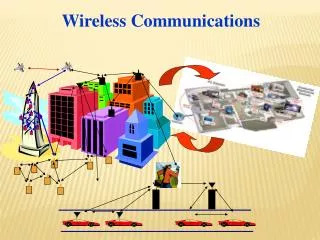
Introduction Wireless Networks
Networking Basics • Two or more connected devices • People can share files, peripherals such as modems, printers and CD-ROM drives etc. • When networks at multiple locations are connected, people can send e-mail,share links to the global internet or conduct video conferences in real time with other remote users.
Networking Components • At least two computers • A network interface on each computer (a device that lets the computer talk to the network) usually an NIC or adapter. • A connection medium usually a wire or cable in case of wired and atmosphere or air in case of wireless communication. • Network operating system software, such as MS Windows 95, NT, AppleShare.
Wireless History • Ancient Systems: Smoke Signals, Carrier Pigeons, … • Radio invented in the 1880s by Marconi • Many sophisticated military radio systems were developed during and after WW2 • Cellular has enjoyed exponential growth since 1988, with almost 3 billion users worldwide today • Ignited the wireless revolution • Voice, data, and multimedia becoming ubiquitous • Use in third world countries growing rapidly • Wifi also enjoying tremendous success and growth • Wide area networks (e.g. Wimax) and short-range systems other than Bluetooth (e.g. UWB) less successful
Future Wireless Networks Ubiquitous Communication Among People and Devices Next-generation Cellular Wireless Internet Access Wireless Multimedia Sensor Networks Smart Homes/Spaces Automated Highways In-Body Networks All this and more …
Challenges • Network Challenges • Scarce spectrum • Demanding/diverse applications • Reliability • Ubiquitous coverage • Seamless indoor/outdoor operation • Device Challenges • Size, Power, Cost • Multiple Antennas in Silicon • Multiradio Integration • Coexistance BT FM/XM GPS Cellular DVB-H Apps Processor WLAN Media Processor Wimax
Evolution of Current Systems • Wireless systems today • 3G Cellular: ~200-300 Kbps. • WLANs: ~450 Mbps (and growing). • Next Generation is in the works • 4G Cellular: Likely OFDM/MIMO • 4G WLANs: Wide open, 3G just being finalized • Technology Enhancements • Hardware: Better batteries. Better circuits/processors. • Link: Antennas, modulation, coding, adaptivity, DSP, BW. • Network: more efficient resource allocation • Application: Soft and adaptive QoS.
4G 3G 2G Future Generations Other Tradeoffs: Rate vs. Coverage Rate vs. Delay Rate vs. Cost Rate vs. Energy Rate 802.11n 802.11b WLAN Wimax/3G 2G Cellular Mobility Fundamental Design Breakthroughs Needed
Quality-of-Service (QoS) • QoS refers to the requirements associated with a given application, typically rate and delay requirements. • It is hard to make a one-size-fits all network that supports requirements of different applications. • Wired networks often use this approach with poor results, and they have much higher data rates and better reliability than wireless. • QoS for all applications requires a cross-layer design approach.
Transmission Fundamentals Chapter 2
Electromagnetic Signal • Function of time • Can also be expressed as a function of frequency • Signal consists of components of different frequencies
Time-Domain Concepts • Analog signal - signal intensity varies in a smooth fashion over time • No breaks or discontinuities in the signal • Digital signal - signal intensity maintains a constant level for some period of time and then changes to another constant level • Periodic signal - analog or digital signal pattern that repeats over time • s(t +T ) = s(t ) - ∞< t < + ∞ • where T is the period of the signal
Time-Domain Concepts • Aperiodic signal - analog or digital signal pattern that doesn't repeat over time • Peak amplitude (A) - maximum value or strength of the signal over time; typically measured in volts • Frequency (f ) • Rate, in cycles per second, or Hertz (Hz) at which the signal repeats
Time-Domain Concepts • Period (T ) - amount of time it takes for one repetition of the signal • T = 1/f • Phase () - measure of the relative position in time within a single period of a signal • Wavelength () - distance occupied by a single cycle of the signal • Or, the distance between two points of corresponding phase of two consecutive cycles
Sine Wave Parameters • General sine wave • s(t ) = A sin(2ft + ) • Figure 2.3 shows the effect of varying each of the three parameters • (a) A = 1, f = 1 Hz, = 0; thus T = 1s • (b) Reduced peak amplitude; A=0.5 • (c) Increased frequency; f = 2, thus T = ½ • (d) Phase shift; = /4 radians (45 degrees) • note: 2 radians = 360° = 1 period
Time vs. Distance • When the horizontal axis is time, as in Figure 2.3, graphs display the value of a signal at a given point in space as a function of time • With the horizontal axis in space, graphs display the value of a signal at a given point in time as a function of distance • At a particular instant of time, the intensity of the signal varies as a function of distance from the source
Frequency-Domain Concepts • Fundamental frequency - when all frequency components of a signal are integer multiples of one frequency, it’s referred to as the fundamental frequency • Spectrum - range of frequencies that a signal contains • Absolute bandwidth - width of the spectrum of a signal • Effective bandwidth (or just bandwidth) - narrow band of frequencies that most of the signal’s energy is contained in
Frequency-Domain Concepts • Any electromagnetic signal can be shown to consist of a collection of periodic analog signals (sine waves) at different amplitudes, frequencies, and phases • The period of the total signal is equal to the period of the fundamental frequency
Relationship between Data Rate and Bandwidth • The greater the bandwidth, the higher the information-carrying capacity • Conclusions • Any digital waveform will have infinite bandwidth • BUT the transmission system will limit the bandwidth that can be transmitted • AND, for any given medium, the greater the bandwidth transmitted, the greater the cost • HOWEVER, limiting the bandwidth creates distortions
Data Communication Terms • Data - entities that convey meaning, or information • Signals - electric or electromagnetic representations of data • Transmission - communication of data by the propagation and processing of signals
Examples of Analog and Digital Data • Analog • Video • Audio • Digital • Text • Integers
Analog Signals • A continuously varying electromagnetic wave that may be propagated over a variety of media, depending on frequency • Examples of media: • Copper wire media (twisted pair and coaxial cable) • Fiber optic cable • Atmosphere or space propagation • Analog signals can propagate analog and digital data
Digital Signals • A sequence of voltage pulses that may be transmitted over a copper wire medium • Generally cheaper than analog signaling • Less susceptible to noise interference • Suffer more from attenuation • Digital signals can propagate analog and digital data
Reasons for Choosing Data and Signal Combinations • Digital data, digital signal • Equipment for encoding is less expensive than digital-to-analog equipment • Analog data, digital signal • Conversion permits use of modern digital transmission and switching equipment • Digital data, analog signal • Some transmission media will only propagate analog signals • Examples include optical fiber and satellite • Analog data, analog signal • Analog data easily converted to analog signal
Analog Transmission • Transmit analog signals without regard to content • Attenuation limits length of transmission link • Cascaded amplifiers boost signal’s energy for longer distances but cause distortion • Analog data can tolerate distortion • Introduces errors in digital data
Digital Transmission • Concerned with the content of the signal • Attenuation endangers integrity of data • Digital Signal • Repeaters achieve greater distance • Repeaters recover the signal and retransmit • Analog signal carrying digital data • Retransmission device recovers the digital data from analog signal • Generates new, clean analog signal
About Channel Capacity • Impairments, such as noise, limit data rate that can be achieved • For digital data, to what extent do impairments limit data rate? • Channel Capacity – the maximum rate at which data can be transmitted over a given communication path, or channel, under given conditions
Concepts Related to Channel Capacity • Data rate - rate at which data can be communicated (bps) • Bandwidth - the bandwidth of the transmitted signal as constrained by the transmitter and the nature of the transmission medium (Hertz) • Noise - average level of noise over the communications path • Error rate - rate at which errors occur • Error = transmit 1 and receive 0; transmit 0 and receive 1
Nyquist Bandwidth • For binary signals (two voltage levels) • C = 2B • With multilevel signaling • C = 2B log2M • M = number of discrete signal or voltage levels
Signal-to-Noise Ratio • Ratio of the power in a signal to the power contained in the noise that’s present at a particular point in the transmission • Typically measured at a receiver • Signal-to-noise ratio (SNR, or S/N) • A high SNR means a high-quality signal, low number of required intermediate repeaters • SNR sets upper bound on achievable data rate
Shannon Capacity Formula • Equation: • Represents theoretical maximum that can be achieved • In practice, only much lower rates achieved • Formula assumes white noise (thermal noise) • Impulse noise is not accounted for • Attenuation distortion or delay distortion not accounted for
Example of Nyquist and Shannon Formulations • Spectrum of a channel between 3 MHz and 4 MHz ; SNRdB = 24 dB • Using Shannon’s formula
Example of Nyquist and Shannon Formulations • How many signaling levels are required?
Classifications of Transmission Media • Transmission Medium • Physical path between transmitter and receiver • Guided Media • Waves are guided along a solid medium • E.g., copper twisted pair, copper coaxial cable, optical fiber • Unguided Media • Provides means of transmission but does not guide electromagnetic signals • Usually referred to as wireless transmission • E.g., atmosphere, outer space
Unguided Media • Transmission and reception are achieved by means of an antenna • Configurations for wireless transmission • Directional • Omnidirectional