Download
1 / 33
330 likes | 334 Views
Controls Overview April, 2005. Outline Goals Status update Resources Design Slides for Global Systems Task descriptions Next 12 months Conclusions Note: As this is being recorded – please add ” it is my impression” and “we expect “ wherever appropriate. LCLS Control System Goals.

E N D
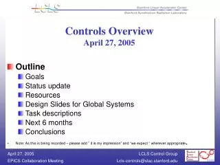
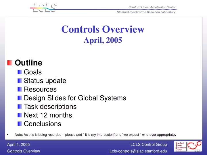
Controls OverviewApril, 2005 • Outline • Goals • Status update • Resources • Design Slides for Global Systems • Task descriptions • Next 12 months • Conclusions • Note: As this is being recorded – please add ” it is my impression” and “we expect “ wherever appropriate.
LCLS Control System Goals • Provide a fully integrated control system to support the construction, test, installation, integration, operation and automation of the LCLS Accelerator • Standardize on all devices and components across all subsystems. • Identify all data either by pulse id, beam pulse related time stamp, or 500 msec rough time stamp. • Full integration with the SLC – timing, use of LCLS data in SLC high level applications, and use of SLC data in LCLS • Work with ESD to provide an upgrade path for the SLC
Update May 2004 – April 2005 • 3 month continuing resolution • Acquire personnel • 8 project engineers – Koturri, Lucchini, Allison, Straumann, Murray, Fairley, Rogind, (offers being made to junior engineer, jobs open for junior proj. eng) • 1 low level programmer (offer being made to junior engineer) • 3 board designers – (support from ESD, evaluating existing designs, interviewing • Steve Lewis on controls at LLNL • Detailed designs to be completed Sept. with costs revamped • Facility Controls, XRay Transport are integrated into control design (details remain) • Prototypes in test: • PNet – hardware design complete, driver functional, tests needed • Timing – hardware from SLS being put into test • Power Supply – hardware from SLS in test for stability and precision • Video – cameras in test • Design efforts ready for prototyping: LLRFand BPM • SLC-Aware IOC is 70% complete. • Prototypes needed for 120 Hz fast feedback and position controllers.
Personnel – Resources Ctl. Elec. Engineer Ctl. Sr. Elec. Tech. Ctl. Elec Tech. Pwr. Elec. Engineer Pwr. Sr. Elec. Tech. Control Prog. 2004 2.42 .56 .07 1.94 .42 .81 2005 10.37 3.44 .60 1.39 .86 10.18 2006 8.12 2.66 2.20 .32 .31 10.29 2007 6.07 1.90 4.63 .51 .72 6.32 2008 3.26 .77 .62 .10 .05 6.56 Total 30.24 9.33 8.12 4.26 2.37 34.17 Ramp up plan: offset 3 months. We are borrowing all of our hardware support. We need some LCLS in-house support
Integration with the SLC Control System EPICS W/S Distributed Applications SLC Alpha All High Level Apps EPICS W/S Distributed Applications EPICS W/S Distributed Applications Xterm Xterm Xterm EPICS W/S Distributed Applications Xterm EPICS WS Distributed High Level Applications SLC Net (Data Communication) KISNet (fast closed loop control data) PNet (Pulse ID / User ID) MPG Ethernet (EPICS Protocol) micro Micro emulator I/OC (SLC-aware) EVG Camac I/O RF reference clock
Global Communication Buses EPICS W/S Distributed Applications EPICS W/S Distributed Applications SLC Alpha Apps EPICS W/S Distributed Applications Xterm Xterm EPICS W/S Distributed Applications Xterm EPICS WS Distributed High Level Applications Xterm Fast Feedback over Ethernet? SLC-Net over Ethernet Channel Access Vacuum Ctrl EVR Pwr Supply Ctrl C P U E VG EVR LLRF EVR Diag C P U HPRF I/O Boards C P U C P U IOC IOC IOC 16 triggers 16 triggers Single Bunch Beam Dumper Drive Laser Off Machine Protection Beam Code + EPICS Time + EPICS Events
Timing Nsec resolution on the timing gates produced from the Event Rcvr 20 psec jitter pulse to pulse Event generator passes along beam code data from SLC Event generator sends events to receivers including: 360 Hz, 120 Hz, 10 Hz and 1 Hz fiducials last beam pulse OK Machine mode EPICS time stamp Event receivers produce to the IOC interrupts on events data from the event generator in registers 16 triggers with configurable delay and width 476 MHz RF Reference SLC micro Master Pattern Generator 128 bit beam code @ 360 Hz FIDO 119 MHz w/ 360 Hz fiducial Vacuum Ctrl EVR Power Supply Ctrl C P U E VG EVR LLRF EVR Diag C P U HPRF I/O Boards C P U C P U IOC IOC IOC 16 triggers 16 triggers Single Bunch Beam Dumper Drive Laser Off Machine Protection Beam Code + EPICS Time + EPICS Events
SLC Net “Micro” Communication Provides data to SLC Applications from EPICS Operates at 10 Hz (not beam synched) Requires significant development in the IOC to emulate SLC “micro” in the IOC On an application by application basis we will evaluate what functions to provide SLC Alpha Apps Xterm Xterm Xterm Xterm SLC-Net over Ethernet Vacuum Ctrl EVR Pwr Supply Ctrl C P U E VG EVR LLRF EVR Diag C P U HPRF I/O Boards C P U C P U IOC IOC IOC
Channel Access EPICS W/S Distributed Applications EPICS W/S Distributed Applications SLC Alpha Apps EPICS W/S Distributed Applications Xterm Xterm EPICS W/S Distributed Applications Xterm EPICS WS Distributed High Level Applications Xterm Channel Access Vacuum Ctrl EVR Power Supply Ctrl C P U E VG EVR LLRF EVR Diag C P U HPRF I/O Boards C P U C P U IOC IOC IOC A channel access server in SLC provides data from existing SLC micros to EPICS applications All IOCs have both a channel access server to allow access and a client to have access Channel access provides read/write by all clients to all data with a server. All EPICS high level applications are channel access clients that may or may not have a server.
Fast Feedback Fast feedback is required to run at 120 Hz Values will be transmitted from RF and selected diagnostics to Power Supply and RF IOCs The communication needs to be reliable, verifiable, and have a well thought out degradation The entire time budget to read, transmit, commute, control, and settle is 8.3 msec First estimates are that the control system can use 2 msecs to transmit and receive the data Can this be done over a common Ethernet with adequate bandwidth – or is a dedicated one needed? Fast Feedback over Ethernet? Vacuum Ctrl EVR Power Supply Ctrl C P U E VG EVR LLRF EVR Diag C P U HPRF I/O Boards C P U C P U IOC IOC IOC
Machine Protection Machine protection is used here to define faults requiring global mitigation Response time is under 8 msec There are two mitigation devices: Single Beam Dumper - which prohibits the beam from entering the undulator Drive Laser Off – which prohibits beam from entering the cavity Action must also be taken to reduce the repetition rate of the beam This new design is required to interrupt the beam before the next beam pulse. Vacuum Ctrl EVR Par Supply Ctrl C P U E VG EVR LLRF EVR Diag C P U HPRF I/O Boards C P U C P U IOC IOC IOC Single Beam Dumper Drive Laser Off Machine Protection
LCLS Project Engineering Tasks • 1 RF Control - Koturri • 3 Diagnostics – Straumann, Murray, tbd Toroids & Faraday Cups, Beam Stops, Profile Monitors & Video Devices, Wire, Scanners, Bunch Length Monitors & E/O Diagnostics, Beam Position Monitors, Collimators, All other stops • Gun Laser and Drive Control – Contract Out • 1 Vacuum – Job Ad Open • 1 Magnet Power Supply Control IOC and software - Luchini • 1 Beam Containment / Personnel Protection / Machine Protection - Chevstov • 1 Low Level Engineer - Norum • 2 High Level Application Engineers – Fairley, Rogind • 1 RDB Manager – need to place job ad • 1 System manager – need to place job ad • 1 Group Leader
LCLS Software Tasks – Purchase/Steal/Develop • SLC-aware IOC – 70% complete. Expected completion June 1, 2005. • Machine Protection / Mitigation (look at SNS and JLAB) • Master pattern generator (look at PSI/Diamond) – being set up • Fast Feedback Communication – need to prototype • High Level Applications (Matlab or XAL) • Correlation Plots (look at JLab) • Fast Feedback Loops • Emittance reconstruction from wire scans and profile monitors • Profile monitor image analysis for slice emittance with the transverse cavity • Beam Steering and online orbit modeling • Beam Steering “scans” to emittance reconstruction from wire scans and profile monitors
LCLS Software Tasks – Purchase/Steal/Develop • Data Archiving to support all phases of the project (SNS) • Operator Display Tools / Synoptic, Plots, Waveform, Image (EDM) • Alarm Management (ALH, CMLOG) • Electronic Log (DESY, JLAB) • High Level Application Support: Matlab, XAL, Python • Control System Configuration Tools (VDCT, RDB) • Relational Database Management in all project aspects (Based on SNS, PEP) • Naming Standard (PEP)
LCLS Hardware Tasks – Purchase/Steal/Develop • Global • New timing boards – Master Pattern Generator and Event Receiver Boards (PSI,DIAMOND) • Machine Protection System (SNS/JLAB) – needs to be evaluated • RF Control – In-house analog with COTS ADCs and DACs • Diagnostics • Toroids & Faraday Cups • Beam Stops • Profile Monitors & Video Devices – evaluating commercial cameras • Wire Scanners • Bunch Length Monitors & E/O Diagnostics • Beam Position Monitors – in-house analog with COTS ADCs and DACs • Collimators • All other stops • Gun Laser and Drive Control – Integrate Thales Controls either device layer or Labview • Vacuum Standards – being finalized • Magnet Power Supply Controllers (PSI) – in test at SLAC • Beam Containment / Personnel Protection – through first review
Next 12 months • Finish hiring: • hardware support – EEs and Techs • Complete hiring actions on project engineers and programmers. • Acquire RDB support. • Complete detailed designs per subsystem and have them reviewed – revamp costs – by the end of this FY. • Integrate the Experimental Hall into the control system. • Complete evaluation/test of PNet, Timing, LLRF, PS, and BPM • Complete the SLC-Aware IOC • Complete first article120 Hz Fast Feedback • Complete first article video diagnostics • Complete first article motion control • Complete first article vacuum • Complete first article MPS • Integrate Laser Control
Conclusions • Control engineers are in place for all major subsystems. • The WBS has been reorganized to move all of the design activities into global controls under 1.1.3.5. Signature authority for all x.x.2 leve WBS is shared. • The SLC-aware IOC and SLC to EPICS timing issues are well on the way to being resolved. • Hardware components have been identified for most of the risky areas. MPS needs attention. PPS needs to complete the citizen review. • By the end of this year, hardware designs should be proven as prototypes and the schedule and budget revamped to reflect the final design desicisions.
Injector Subsystem Designs Timing C P U EVR Digitizer C P U EVR T C M T C M T C M T C M T C M C P U EVR B I B O G A D C MPS? 1.2.2.3.3 1.2.2.3.2 1.2.2.2 PM Chassis LEAD L E A D L E A D SLC Actuator Preamps Mcond chassis MKSU LLRF RF Equipment Toroids Faraday Cups 4 Faraday Cups with YAGs, share toroid IOC 6 instances (1 for each klystron), 1 IOC in total 5 Toroids 1 IOC
Injector Subsystem Designs Ethernet Beam Code + EPICS Time C P U EVR B I B O C P U EVR B I B O DAC MPS 1.2.2.3.4 1.2.2.3.5 Turn Off PM Chassis PM Chassis Cameras Electronics Lamps & Actuator Actuator Tune Up Dump Profile Monitors 11 Profile Monitors (4 YAGs, 7 OTRs), 1 IOC 1 Tune Up Dump, shares toroid IOC
Injector Subsystem Designs Beam Code + EPICS Time C P U B I B O A O GADC S M C T L EVR C P U EVR B P M B P M B P M B P M B P M B P M B P M C P U EVR A I GADC A O To llrf Turn off 1.2.2.3.6 1.2.2.3.7 1.2.2.4 1.2.2.5 Motor Controls Ilock Chs (2) Cameras Electronics Thermocouples E/O Diagnostic BPM Pickups Gun Laser and Heater Ctrls 48 Mirror Motors, 4 Shutters 1 Camera, Joulemeter 1 IOC 21 BPMs 3 IOCs 1 Pulse length meas. share toroid IOC
Injector Subsystem Designs Beam Code + EPICS Time LLRF? BCS? Network & Crates C P U E VG C P U EVR G PIB ? B I B O A I A O A I PPS MPS 1.2.2.6 1.2.2.8 1.2.2.7 119 MHz w/ 360Hz Fid PNET SLAC PMVC Power Supplies GP307 IG HP937 CCG FIDO SLC Timing 4 bl valves 30 gauges 30 ion pumps Manual valves into MPS?
Injector Subsystem Designs Beam Code + EPICS Time 1.2.2.10 1.2.2.9 C P U EVR RTD SAM C P U EVR B I O A I O Ethernet Control Logix PLC (3) Control Logix PLC (1) PS Reg Interface temperatures 1.2.16.4 1.2.16.3 1.2.16.1 MCOR Power Supplies (4?) Magnet Power Supplies (4) Klixon Boxes PPS Gates Laser PPS Gates High Current High Precision Magnets w/ KLIXONS (4) Low Current Fast Corrector and Quadrupoles Magnets Tone Receiver
LINAC Subsystem Designs Ethernet Timing C P U EVR DAC C P U EVR T C M T C M T C M T C M T C M GADC T C M C P U EVR B I B O DAC 1.3.2.6.3 1.3.2.5 1.3.2.6.5 PM Chassis LEAD L E A D L E A D SLC Cameras Electronics Lamps & Actuator Preamps MKSU LLRF RF Equipment Profile Monitors Toroids 6 Toroids 1 IOC 1 Phase Control 24/30 Remaining in SLC 20 Profile Monitors 1 IOC
Ethernet LINAC Subsystem Designs Beam Code + EPICS Time B I C P U B I B O C P U EVR B P M B P M B P M B P M B P M B P M B P M G A D C C P U EVR SM A D C B O C P U EVR B I B O DAC 1.3.2.6.2 1.3.2.6.1 1.3.2.6.5 1.3.2.6.4 PM Chassis PM Chassis HVPS Motor elec Cameras Electronics Lamps & Actuator LVDT Actuator Photo Tube Stoppers Wire Scanners And Motors BPM Pickups E/O Diagnostics 20 Wire scanners – 11 new, 1 IOC 143 BPMs 15 IOCs 1 Pulse length meas.
LINAC Subsystem Designs Beam Code + EPICS Time C P U EVR B I B O C P U EVR B I B O A D C C P U EVR B I B O A D C C P U EVR B I B O G A D C MPS 1.3.2.6.9 1.3.2.6.10 1.3.2.6.11 1.3.2.6.7 Turn Off PM Chassis PM Chassis PM Chassis PM Chassis Actuator Actuator Actuator Actuator Mcond chassis Single Beam Dump E Beam Dump Bunch Length Monitors Protection Collimator
LINAC Subsystem Designs Beam Code + EPICS Time Timing C P U EVR DAC GADC C P U EVR B I B O S M 1.3.2.6.12 1.3.2.6.13 PM Chassis SLC SLC Actuator MKSU MKSU LLRF X – Band Accelerator Structure Movable Collimator
LINAC Subsystem Designs Beam Code + EPICS Time LLRF? BCS? EVR C P U EVR G PIB ? B I B O A I A O A I PPS MPS 1.3.2.9 1.3.2.8 SLAC PMVC Power Supplies GP307 IG HP937 CCG SLC Timing 4 bl valves gauges ion pumps 24 sets of timing receiver modules 4 chassis for each type of interface
LINAC Subsystem Designs Beam Code + EPICS Time 1.3.2.4 C P U EVR C P U EVR BBUS VMIC Ethernet Control Logix PLC (3) PS Reg Interface 1.3.2.2 1.3.2.6.8 MCOR Power Supplies 1.3.2.1 1.3.2.3 Magnet Power Supplies Klixon Boxes P L I C PPS Gates BSOIC BSOIC High Current High Precision Magnets w/ KLIXONS (4) Low Current Fast Corrector and Quadrapoles Magnets MPS Beam Containment System Tone Receiver
Undulator Subsystem Designs Beam Code + EPICS Time EVR P I E Z O C P U A I S M C T L C P U EVR C P U EVR SM A D C G A D C 1.4.2.2.2 1.4.2.2.1 1.4.2.2.6 Motor Controls Motor Controls Motor Controls LVDT Wire Position Read-backs Phase Corrector Motion Fine Motion Control (strong back cradle motion) Motors Wire Scanners And Motors 11 wire scanners 233 motors 4 * 33 controllers
Undulator Subsystem Designs Beam Code + EPICS Time S M C T L C P U EVR GADC C P U EVR B P M B P M B P M B P M B P M B P M B P M C P U EVR GADC C P U EVR 1.4.2.3.1 1.4.2.2.7 1.4.2.3.2 1.4.2.3.2 Motor Controls Downconverters BPM Pickups Scanning Wires ADCs Macroscopic Motion Control Charge Monitors (Toroid) 2 Charge monitors 2 IOCs 33 BPMs 33 IOCs 3 IOCs 55 controllers
Undulator Subsystem Designs Beam Code + EPICS Time Ethernet Ethernet C P U EVR B I B O DAC A I C P U EVR B I B O DAC A I A I C P U A I 1.4.2.5 1.4.2.4.1 1.4.2.4.3 Cameras Electronics Lamps & Actuator Cameras Electronics Lamps & Actuator Profile Monitors Strongback Temperature Observation Video 66 temperatures 11 OTRs 7 stations
Undulator Subsystem Designs Beam Code + EPICS Time LLRF? BCS? C P U M P S C P U G PIB B I B O A I A O A I C P U PPS Ethernet 1.4.2.7 1.4.2.6.4 1.4.2.6.1 RGA SLAC PMVC Power Supplies GP307 IG HP937 CCG Cherenkov Detector, Gamma Ray Detector, Temperature Gauge ? bl valves 2 gauges 33 ion Pumps * 6 Tone Receiver 2 RGAs