Download
1 / 38
380 likes | 389 Views
ISE 370 Industrial Automation Instructor: Thomas Koon. Electrical Consideration for Industrial Automation. Topics of Discussion. Basic Electric Systems Factory Automation Concerns Motors Machine Vision Basics. Electric Current. A.C. Systems – Single Phase.

E N D
ISE 370 Industrial AutomationInstructor: Thomas Koon Electrical Consideration for Industrial Automation Paul Blythe - Binghamton University
Topics of Discussion • Basic Electric Systems • Factory Automation Concerns • Motors • Machine Vision Basics Paul Blythe - Binghamton University
Electric Current Paul Blythe - Binghamton University
A.C. Systems – Single Phase • Three Load voltages may be obtained: • 120V single phase 2 wire • 240v single phase 2 wire • 120/240V single phase 3 wire Paul Blythe - Binghamton University
AC Waveform 3 Phase Paul Blythe - Binghamton University
Three Phase Systems • Delta Connected System • No Neutral • Line to Line Voltages Only • Easier to Balance Paul Blythe - Binghamton University
Wye Connected System Load Voltages Obtained From 480V System • 277 volt single phase two wire (L-N) • 480V single Phase, two wire • 480V single Phase, three wire • 480/277 V three phase, four wire Paul Blythe - Binghamton University
Three Phase Systems • What is the line to neutral voltage Paul Blythe - Binghamton University
Three Phase Systems Paul Blythe - Binghamton University
Three Phase Systems • Remember to balance your load • Step 1: Determine the loads' VA ratings. • Step 2: Put one-third of the 3-phase load on Phase A, one-third on Phase B, and one-third on Phase C. • Step 3: Put one-half of the single-phase, 208V load on Phase A and Phase B, or Phase B and Phase C, or Phase A and Phase C. Paul Blythe - Binghamton University
Electrical Code Summary Paul Blythe - Binghamton University
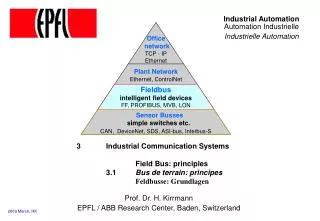
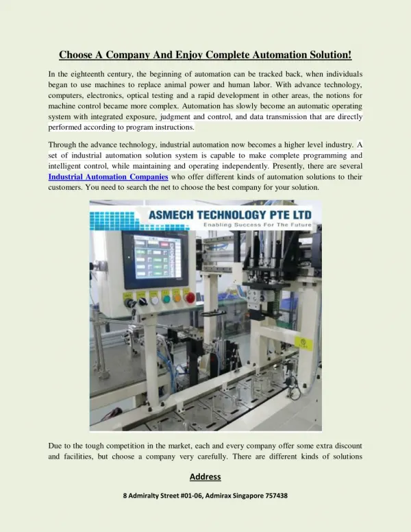
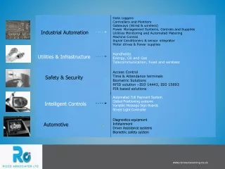
Industrial Automation Paul Blythe - Binghamton University
Common Industrial Protocol (CIP) • Common Industrial Protocol (CIP) is an open industrial protocol for industrial automation applications.. • Collection of manufacturing automation applications – control, safety, synchronization, motion, configuration and information. • It allows users to integrate these manufacturing applications with: • Enterprise-level Ethernet networks • Internet • EtherNet/IP, DeviceNet, CompoNet and ControlNet. Paul Blythe - Binghamton University
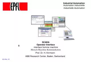
Some Automation Considerations Paul Blythe - Binghamton University
Automation Consideration Paul Blythe - Binghamton University
Operator Safety Light Curtain is the most common safety device on automated machines Presence Sensing Device Stop Machine Motion Paul Blythe - Binghamton University
RS Logix 5000 Controller Paul Blythe - Binghamton University
Ladder Logic Programming Paul Blythe - Binghamton University
What is an Electric Motor? • Electromechanical device that converts electrical energy to mechanical energy • Mechanical energy used to e.g. • Rotate pump impeller, fan, blower • Drive compressors • Lift materials • Motors in industry: 70% of electrical load Paul Blythe - Binghamton University
How does an electric motor work? Paul Blythe - Binghamton University
Electric Motors Alternating Current (AC) Motors Direct Current (DC) Motors Synchronous Induction Separately Excited Self Excited Single-Phase Three-Phase Series Compound Shunt Type of Electric Motors Paul Blythe - Binghamton University
DC Motors • Field pole • North pole and south pole • Receive electricity to formmagnetic field • Armature • Cylinder between the poles • Electromagnet when current goes through • Linked to drive shaft to drive the load • Commutator • Overturns current direction in armature Paul Blythe - Binghamton University
DC Motors • Speed control without impact power supply quality • Changing armature voltage • Changing field current • Restricted use • Few low/medium speed applications • Clean, non-hazardous areas • Expensive compared to AC motors Paul Blythe - Binghamton University
AC Motors • Electrical current reverses direction • Two parts: stator and rotor • Stator: stationary electrical component • Rotor: rotates the motor shaft • Speed difficult to control • Two types • Synchronous motor • Induction motor Paul Blythe - Binghamton University
AC Motors – Synchronous motor • Constant speed fixed by system frequency • DC for excitation and low starting torque: suited for low load applications • Can improve power factor: suited for high electricity use systems • Synchronous speed (Ns): F = supply frequency P = number of poles Ns = 120 f / P Paul Blythe - Binghamton University
AC Motors – Induction motor • Most common motors in industry • Advantages: • Simple design • Inexpensive • High power to weight ratio • Easy to maintain • Direct connection to AC power source Paul Blythe - Binghamton University
AC Motors – Induction motor Components • Rotor • Squirrel cage: conducting barsin parallel slots • Wound rotor: 3-phase, double-layer, distributed winding • Stator • Stampings with slots to carry 3-phase windings • Wound for definite number of poles Paul Blythe - Binghamton University
Electromagnetics Rotor Stator AC Motors – Induction motor How induction motors work • Electricity supplied to stator • Magnetic field generated that moves around rotor • Current induced in rotor Rotor produces second magnetic field that opposes stator magnetic field Rotor begins to rotate Paul Blythe - Binghamton University
Variable Speed AC MotorSelection decisions Both steel and cast iron construction Enclosed or open enclosures Non-vent or fan cooled Foot or face mounting. Paul Blythe - Binghamton University
Example of 75HP, 1800 RPM Motor Applications • Extruders • Forest Products Paul Blythe - Binghamton University
Machine Vision Illumination Basics Thoughts for Today: • Light is governed by the laws of physics • Reliable lighting (not ambient) is important for a successful installation • Shiny surfaces (specular) are particularly challenging • Use Scientific Methods to Analyze and Diagnose Paul Blythe - Binghamton University
Machine Vision Basics • The Two Cornerstones • Structure or Geometry • Illumination wavelength or color Paul Blythe - Binghamton University
Source Comparisons Paul Blythe - Binghamton University
Optical Characteristics of an LED Paul Blythe - Binghamton University
Cameras Analog and digital Color and monochrome UV, visible, and IR Area scan and line scan CCD and CMOS Connectivity and interfaces Other things to consider Paul Blythe - Binghamton University
Cameras • Area and Line Scan Cameras • Line scan cameras produce high resolution at much lower price • Requires movement of the camera or object • More limited lens selection due to array size • UV, Visible, and IR • Standard cameras • Sensitivity is possible down to 200 nm • Near, Mid, and Far IR generally require different materials for the imager • These materials still have a high cost • Need different material for the optics in these ranges Paul Blythe - Binghamton University
CCD and CMOS • CCDs provide higher quality images • CMOS offers lower cost by leveraging economies of scale • Design of CMOS allows for • Anti blooming control • Real area of interest scanning • Increased onboard processing • Higher speeds • CMOS generally needs to be done in larger runs • CCDs will continue hold the lower volume markets Paul Blythe - Binghamton University
Thank You ? Paul Blythe - Binghamton University