Download
1 / 105
1.11k likes | 1.46k Views
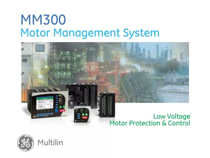
g. Multilin. MM300 Motor Management System . Low Voltage Motor Protection & Control. Introduction MM300 Key Benefits Hardware Overview Electrical Overview Protection Overview Monitoring & Metering Communications Graphic Display Panel EnerVista™ MM300 Setup Software Order Codes.

E N D
g Multilin MM300Motor Management System Low Voltage Motor Protection & Control
Introduction MM300 Key Benefits Hardware Overview Electrical Overview Protection Overview Monitoring & Metering Communications Graphic Display Panel EnerVista™ MM300 Setup Software Order Codes MM300Motor Management System Agenda
MM300Advanced Motor Management • Advanced Automation • Eliminate Stand-alone dedicated PLC, Package controllers • Pre-canned starter logic: FVNR, FVR, Two speed, wye-delta, inverter/soft-start • Process interlocks for starter supervision • FlexLogic™ for sequencing applications, Custom starter/interlock logic • Multiple I/O options • Comprehensive Motor Protection • Thermal Overload, Mechanical Jam • Unbalance • Thermistor • Ground Fault (CBCT) • UV, Underpower RTD (Optional) • Powerful Comms for Easy Integration • Modbus RTU (RS485) standard • Ethernet with Modbus TCP • + Fieldbus Optinal • Profibus DP • DeviceNet • Powerful Metering • RMS currents, %UB, Thermistor • AUX voltage, frequency, power • 3 Phase voltage, metering (Optional) • Eliminate stand-alone metering • Motor Diagnostic Information • Sequence of Events Data • Motor Learned Data • Waveform Capture • RMS Data Logger • Small Footprint • Conformal Coating Standard • -20°C to +70°C Continuous Operation
MM300Motor Management System The MM300 is a modular based Motor Protection and Control system designed specifically for Low Voltage Motor Applications • Key Applications • Designed to meet the requirements of IEC and NEMA Class MCC Buckets • Panel Mount option for Stand alone motor applications • Powerful and Flexible protection to meet the specific requirements of Low Voltage AC Motor Applications • Conveyor Belts • Fans • Pumps • etc.
g imagination at work MM300 Key Benefits
MM300 . . . Key Benefits Functionality Reliable protection for secondary & backup purposes
Certifications & Form Factor • Fully Certified and Tested • CSA, UL, CE, IEC, ISO • IEC 60068-2-38 Temperature / Humidity Cycle • IEC Vibration Tested: 57 – 150 Hz for DIN Rail installations, Sinusoidal (high-vibration installation mode) • Small Form Factor • Compact and Modular Design • Designed for IEC or NEMA MCCs • Remote Mounted Control Panel (Door + DIN Rail Mounting)
Flexibility for Standardization • Flexibility & Customization • Direct connect up to 690V (No requirement for additional CT’s & VT’s) • 1A & 5A Internal CT’s • Programmable and Expandable I/O eliminates PLCs or other discrete relay devices • Mounting Options (Door + DIN Rail, Panel Mount, Screw Mount) • Scalable Protection & Control Logic Functionality • Removable terminal blocks
MM300 . . . Key BenefitsSize • Compact • Base Unit • 120 mm (W) x 90 mm (H) x 123 mm (D) • 4.74” (W) x 3.54” (H) x 4.84” (D) • Color HMI Display • 154 mm (W) x 103 mm (H) x 15 mm (D) • 6.06” (W) x 4.05” (H) x 0.60” (D) • Control Panel • 75 mm (W) x 75 mm (H) x 31 mm (D) • 2.95” (W) x 2.95” (H) x 1.22” (D)
g imagination at work Hardware Overview
MM300 . . . Hardware Overview The MM300 Motor Protection system consists of 4 main components Color HMI Display Base Unit Control Panel Expansion Module
MM300 . . .Hardware Overview User Interface • Front Panel Controls • Integrated Device Control • Simple to Use • Dedicated control keys • Graphical Display • Multi-language Support • Large Metering Values • Wide viewing angle • Ease of Use • Graphical Interface • LED Indication • Motor status • Alarm Indication • System Status • Communication Status • Additional user LEDs • Mounting Options • DIN Rail • Through Door • IP54 Rated Display • Security • Role Based Access • Integrated Functionality • Protection, Metering, Control • Event Recorder • Data Logger • Waveform capture • Entry Level Control Panel • Control keys • LED Indication • Front Port Access • USB for Laptop Connection • Soft key Navigation • Graphical Module Control
MM300 . . .Electrical OverviewTerminal Connections Expansion module attaches to base unit with a single connector RS485 Communications and Thermistor Input Optional Profibus DP or DeviceNet Fieldbus protocols 3 Phase and 1 Residual GND CT Inputs Optional 3 phase Voltage Module Optional Expansion Module Allows additional Digital I/O, RTD, or Voltage inputs • I/O card includes: • 2 Contactor Outputs (Form A) • 6 Programmable inputs • Single Phase VT input (60-300Vac) Optional RTD Module with three RTD inputs Optional TCP / IP Ethernet Switched Power Supply allows AC or DC control voltage Core Balance Ground CT Input
MM300 . . .Hardware OverviewDimensions – Base Unit • Small foot print • Modular Design • 2 expansion modules can be added. • Expansion modules are 56mm (2.2”)
MM300 . . .Hardware Overview Mounting options • Provides a flexible footprint for smaller buckets • Display can be mounted up to 6 feet away
MM300 . . .Hardware Overview Mounting options – Din rail • Easy insertion and removal of unit • MM300 slides straight in and the din clips are closed
MM300 . . .Hardware Overview Modules – Removal and Inserting • A slot track is provided • Align the new card with the track and slowly slide the card in place. • Use the captive screws to anchor the card in place.
g imagination at work Electrical Overview
Built-In Starter Logic • • Full-voltage non-reversing (FVNR) • • Full-voltage reversing (FVR) • • Two-speed (TS) • • Wye-delta open transition (WDOT) • • Inverter (I) • • Soft start (SS) By selecting a pre-defined starter, inputs and outputs are automatically assigned
Process Interlocking • Before Motor Start • Ensure all support, safety and process permissives are ready • At start, ride-through for normal process conditions may be applied • Post Motor Start • Ensure that process flow, pressure, temperature or other limits are not in violation • Provide ride-through for intermittent violations
Process Interlocking Examples • ON START • Centrifugal blower/fan no airflow alarm delayed on start up until static and friction head pressure is established against ductwork by using “start override” delay • DURING RUN • Cryogenic fluid flashes at intervals in a positive displacement pump causing cavitation and momentary drop in differential pressure across pump. Differential pressure alarm delayed using”running override.”
g imagination at work Protection Overview
Protection Features Goals: Detect ground fault, abnormal electrical conditions, abnormal process conditions and thermal issues
MM300 . . .Protection Features Thermal Model • Thermal Overload protection for both the Stator and Rotor • RTD and Unbalanced Biasing of the Thermal Model provides enhanced protection Nameplate data used to program thermal model • Full Load Amps • Safe Stall Ratio Standard Overload Curves • 15 Standard Multilin Curves with multipliers available • Based on motor thermal damage curves provided by the manufacturer • Automatically adjusted for Hot and Cold motor conditions
Protection: Thermal Unbalance Current Derating Use #8 for NEMA
Protection: Thermal RTD Biasing • Provides temperature-based protection against thermal damage • Minimum is Ambient • Midpoint is Rated Rise over Ambient, plus Calculation of Hot/Cold Stall Ratio • Maximum is Insulation Class Maximum
Protection: Thermal Cooling Time Constant • Uses Running and Stopped Cooling Time Constants • Time Constant defined as time it takes to get 63% to Ambient after 100% temperature is obtained
MM300 . . .Protection Features Motor Starting Start Inhibit • Ensures motor has cooled sufficiently to allow a successful motor start command • Compares learned starting temperature and actual motor temperature Additional Motor Starting Protection • Acceleration Trip • Starts per Hour • Time Between Starts • Start Inhibits • Backspin Timer • Restart Blocks
MM300 . . .Protection Features Current • Residual Ground Fault • Sensitive Ground Fault • Unbalance • Single phase • Mechanical jam/rapid trip Voltage & Power • Under / Over Voltage • Phase reversal • 3 Phase Underpower
MM300 . . .Protection FeaturesAdvanced Process Control Reduced Voltage Starting • Controls transition of reduced voltage starters • Based on current level and timers Under Voltage Auto-Restart • Automatically issues a start command for system or process related faults • Based on timers and optional system voltage Remote Start / Stop Commands • Serial or hardwired Start and Stop commands operate Contactor Outputs for remote operation of the motor
g imagination at work Monitoring & Metering
MM300 . . .Monitoring & Metering Current and voltage • Phase Current (RMS / Phasor) • Residual Ground Fault Current • Sensitive Ground Fault Current • Unbalance current • 3 Phase Voltage (RMS / Phasor) • Frequency • Motor Load