Download
1 / 10
130 likes | 263 Views
Rectified Input Voltage. Input Current. Objective: Review the Similarities and Differences of Both Controllers Highlight the Application Differences That Transitioning Customers Need to Know About. Similarities: Designed to Control PFC Power Stage Average Current Mode Control

E N D
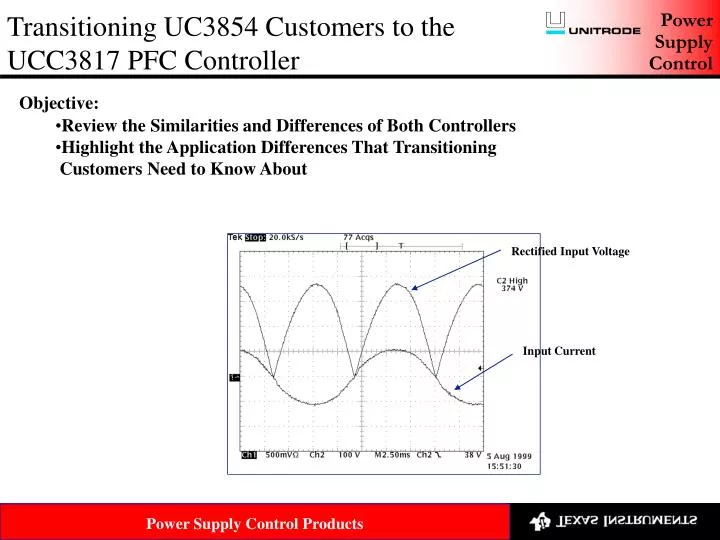
Rectified Input Voltage Input Current • Objective: • Review the Similarities and Differences of Both Controllers • Highlight the Application Differences That Transitioning • Customers Need to Know About
Similarities: • Designed to Control PFC Power Stage • Average Current Mode Control • Achieved Near Unity Power Factor by Shaping the Input Current Waveform • These Controllers Are Typically Designed in Two-stage Systems • Typical Two Stage Power Converter With PFC Front End
Differences: • PWM Modulation • UC3854 Uses Traditional Trailing Edge PWM Modulation • UCC3817 Uses Leading Edge Modulation • Current Amplifier • UC3854 Is Set up in a Non Inverting Configuration • UCC3817 Is Set up in an Inverting Configuration • Voltage Feed Forward(VFF) • UC3854 Generates VFF From the Input and Requires a Two Pole Filter • UCC3817 Generates VFF Internally From the Iac Current and Only • Requires a Single Pole Filter • Multiplier • The Older UC3854 Required a Bias Resistor From the Internal Reference • to the Iac Pin for Proper Operation • The UCC3817 Multiplier Has Better Overall Parametric Performance
PWM Modulation • UC3854 Uses Traditional Trailing Edge PWM Modulation • UCC3817 Uses Leading Edge PWM Modulation • When Properly Synchronized With a Down Stream Converter Can • Have up to 40% Less RMS Current Through the Boost Capacitor Boost Capacitor Ripple Current Comparison Synchronization Circuit
Current Amplifier Configuration • UC3854 Uses a Non Inverting Amplifier Configuration • UCC3817 Uses a Inverting Amplifier Configuration That Can Have Better • Noise Rejection Than the Non Inverting Configuration
Voltage Feed Forward(VFF) • UC3854 Generates VFF From a Voltage Divider That Requires a Two Pole Filter • 5 Components Required to Generate the VFF • UCC3817 Generates the VFF From an Internal Current Source That Requires a • Single Pole Filter • 2 Components Required to Generate the VFF
Multiplier: • The Older UCC3854 Required a Bias Resistor From Vref to Iac For Proper Operation Bias Resistor
Multiplier: • The UCC3817’s Improved Multiplier Performance Improves System • Operation Over a Wider Load Range • Performance Curves Can Be Found in the Data Sheet
Recap Reasons For Transitioning From The UC3854 to The UCC3817 • The UCC3817 Has Better Noise Immunity Because of the Current Amplifier • Configuration • It Takes Fewer Components to Use the UCC3817 in the Application • Leading Edge Modulation When Synchronized Correctly Will Reduce the RMS • Current in the Boost Capacitor • Improved Multiplier Performance Allows the System to Operate With a Wider Load Range
UCC3817 EVM Availability • EVMs Are Available Presently but in Limited Quantities • Contact Judy Pacheco • EVMs Are Presently Being Put Into the TI System and Will Be Available in August