Download
1 / 39
400 likes | 1.07k Views
Pseudobinary Phase Diagram @ 70% Iron. AWS Welding Handbook. Prediction of Weld Metal Solidification Morphology. Schaeffler Diagram. WRC Diagram. AWS Welding Handbook. Hot Cracking. P+S. A few % Ferrite Reduces Cracks But P&S Increase Cracks. AWS Welding Handbook.

E N D
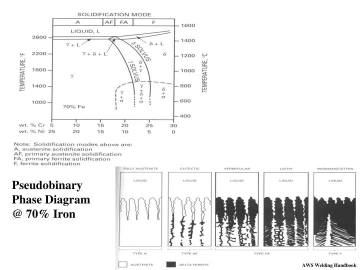
Pseudobinary Phase Diagram @ 70% Iron AWS Welding Handbook
Prediction of Weld Metal Solidification Morphology Schaeffler Diagram WRC Diagram AWS Welding Handbook
Hot Cracking P+S A few % Ferrite Reduces Cracks But P&S Increase Cracks AWS Welding Handbook
Spot Welding Austenitic Stainless Steel • Some Solidification Porosity Can Occur: • As a result of this tendency to Hot Crack when Proper • Percent Ferrite is not Obtained • Because of higher Contraction on Cooling • Suggestions: • Maintain Electrode Force until Cooled • Limit Nugget Diameter to <4 X Thickness of thinner piece • More small diameter spots preferred to fewer Large Spots
Spot Welding Austenitic Stainless Steel Some Discoloration May Occur Around Spot Weld Oxide Formation in HAZ Nugget • Solutions • Maintain Electrode Force until weld cooled below oxidizing Temperature • Post weld clean with 10% Nitric, 2% Hydrofluoric Acid (Hydrochloric acid should be avoided due to chloride ion stress-corrosion cracking and pitting)
Seam Welding Austenitic Stainless Steel Somewhat more Distortion Noted Because of Higher Thermal Contraction • Solution • Abundant water cooling to remove heat Knifeline Corrosion Attack in Austenitic Stainless Steel Seam Welds • Solution • See Next Slide for more description
Chromium Carbide Precipitation Kinetics Diagram 1500 °F 1500 F M23C6 Precipitation 1200 °F 800 F Temperature Chromium Oxide 800 °F M23C6 Chromium-Rich Carbides Intergranular Corrosion Time
Preventative Measures • Short weld times • Low heat input • Lower carbon content in the base material • 304L, 316L • Stabilization of the material with titanium additions • 321 (5xC) • Stabilization with columbium or tantalum additions • 347, 348 (10xC) • Lower nitrogen content (N acts like C)
Projection Welding Austenitic Stainless Steel Because of the Greater Thermal Expansion and Contraction, Head Follow-up is critical • Solution • Press Type machines with low inertia heads • Air operated for faster action In Welding Tubes to tube sheets with Ring projections for leak tight application, electrode set-up is critical • Solution • Test electrode alignment
Cross Wire Welding Austenitic Stainless Steel Often used for grates, shelves, baskets, etc. • Use flat faced electrodes, or • V-grooved electrodes to hold wires in a fixture • As many as 40 welds made at one time
Flash Welding Austenitic Stainless Steel • Current about 15% less than for plain carbon • Higher upset pressure • The higher upset requires 40-50% higher clamp force • Larger upset to extrude oxides out
Super Austenitic • Alloys with composition between standard 300 Austenitic SS and Ni-base Alloys • High Ni, High Mo • Ni & Mo- Improved chloride induced Stress Corrosion Cracking • Used in • Sea water application where regular austenitics suffer pitting, crevice and SCC
The Super Austenitic Stainless Steels are susceptible to copper contamination cracking. RESISTANCE WELDING NOT NORMALLY PERFORMED • Copper and Copper Alloy Electrodes can cause cracking: • Flame spray coated electrodes • Low heat
Nitrogen-Strengthened Austenitic • High nitrogen levels, combined with higher manganese content, help to increase the strength level of the material • Consider a postweld heat treatment for an optimum corrosion resistance Little Weld Data Available
Martensitic • Contain from 12 to 18 percent chromium and 0.12 to 1.20 percent carbon with low nickel content • Combined carbon and chromium content gives these steels high hardenability • Magnetic • Tempering of the low-carbon martensitic stainless steels should avoid the 440 to 540 °C temperature range because of a sharp reduction in notch-impact resistance Applications: Some Aircraft & Rocket Applications Cutlery
Martensitic SS Wrought Alloys are divided into two groups • 12% Cr, low-carbon engineering grades (top group) • High Cr, High C Cutlery grades (middle group) AWS Welding Handbook
From a Metallurgical Standpoint, Martensitic SS is similar to Plain Carbon (12% Chromium) AWS Welding Handbook
Martensitic • Spot Welding • HAZ Structural Changes • Tempering of hard martensite at BM side • Quench to hard martensite at WM side • Likelihood of cracking in HAZ increases with Carbon • Pre-heat, post-heat, tempering helps • Flash Weld • Hard HAZ • Temper in machine • High Cr Steels get oxide entrapment at interface • Precise control of flashing & upset • N or Inert gas shielding
Effect of Tempered Martensite on Hardness As Quenched Loss of Hardness and Strength Hardened Martensite Tempered Martensite Hardness Fusion Zone SS with carbon content above 0.15% Carbon (431, 440) are susceptible to cracking and need Post Weld Heat Treatment HAZ Distance
Ferritic • Contain from 11.5 to 27 percent chromium, with additions of manganese and silicon, and occasionally nickel, aluminum, molybdenum or titanium • Ferritic at all temperatures, no phase change, large grain sizes • Non-hardenable by heat treatment • Magnetic (generally) Applications: Water Tanks in Europe Storage Tanks
FERRITIC STAINLESS STEELS Spot & Seam Welding Because No Phase Change, Get Grain Growth
FERRITIC STAINLESS STEELS Flash Weld • Lower Cr can be welded with standard flash weld techniques • loss of toughness, however • Higher Cr get oxidation • Inert gas shield recommended • long flash time & high upset to expel oxides
Super Ferritic • Lower than ordinary interstitial (C&N) • Higher Cr & Mo • Better corrosion (Cr) & Higher Hot Strength (Mo) AWS Welding Handbook
Increased Cr & Mo promotes Embrittlement • 825F Sigma Phase (FeCr) precipitation embrittlement • 885F Embrittlement (decomposition of iron-chromium ferrite) • 1560F Chi Phase (Fe36Cr12Mo10) precipitation embrittlement Because of the Embrittlement, Resistance Welding is Usually Not Done on These Steels
Precipitation-Hardened • Can produce a matrix structure of either austenite or martensite • Heat treated to form CbC, TiC, AlN, Ni3Al • Possess very high strength levels • Can serve at higher temperature than the martensitic grades Applications: High Strength Components in Jet & Rocket Engines Bombs
Martensitic • Solution heat treat above 1900F • Cool to form martensite • Precipitation strengthen • Fabricated • Semiaustenitic • Solution heat treat (still contain 5-20% delta ferrite) • Quench but remain austenitic (Ms below RT) • Fabricate • Harden (austenitize, low temp quench, age) • Austenitic • Remain austinite • Harden treatment
RC=Rapid Cool to RT SZC= Rapid cool to -100F AC=Air cooled WQ=Water Quenched AWS Welding Handbook
Effect on Aging on the Nugget Hardness in Precipitation-Hardened Stainless Steels Aged Hardness • When Welded in the Aged Condition • Higher Electrode Forces • Post Weld Treatment Annealed Weld Centerline Distance
Precipitation-Hardened • Spot Welding • 17-7PH, A-286, PH15-7Mo, AM350 & AM355 have been welded • Generally welded in aged condition, higher forces needed • Time as short as possible • Seam Welding • 17-7PH has been welded • Increased electrode force • Flash Welding • Higher upset pressure • Post weld heat treatment
Duplex • Low Carbon • Mixture: {bcc} Ferrite (over 50%) + {fcc} Austenite • Better SCC and Pitting Resistance than Austenitics • Yield Strengths twice the 300 Series Early grades had 75-80% Ferrite (poor weld toughness due to ferrite) Later grades have 50-50
Due to the Ferrite: • Sensitive to 885F embrittlement • Sigma Phase embrittlement above 1000F • High ductile to brittle transition temperatures (low toughness) • Solidifies as ferrite, subsequent ppt of nitrides, carbides which reduces corrosion resistance • Rapid cooling promotes additional ferrite • Not Hot Crack Sensitive Resistance Welds generally not recommended because low toughness and low corrosion resistance Unless post weld solution anneal and quench.
Some Applications
Method of Making an Ultra Light Engine Valve Deep Drawing of Plain Carbon Steel or Stainless Steel Stainless Steel Cap Resistance Weld Larson, J & Bonesteel, D “Method of Making an Ultra Light Engine Valve” US Patent 5,619,796 Apr 15, 1997