Download
1 / 47
470 likes | 603 Views
Debug Status Register. A Debug Status Register allows the exception 1 handler to easily determine why it was invoked. It can be invoked as a result of one of several events: 1) DR0 Breakpoint fault/trap. 2) DR1 Breakpoint fault/trap. 3) DR2 Breakpoint fault/trap.

E N D
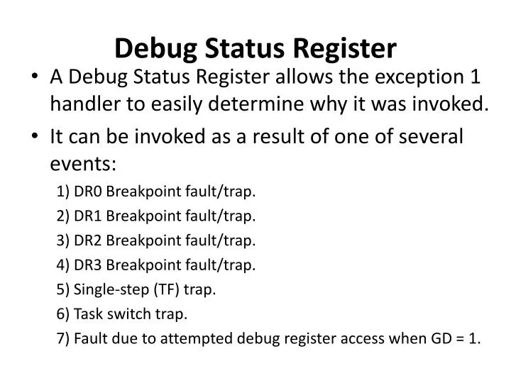
Debug Status Register • A Debug Status Register allows the exception 1 handler to easily determine why it was invoked. • It can be invoked as a result of one of several events: 1) DR0 Breakpoint fault/trap. 2) DR1 Breakpoint fault/trap. 3) DR2 Breakpoint fault/trap. 4) DR3 Breakpoint fault/trap. 5) Single-step (TF) trap. 6) Task switch trap. 7) Fault due to attempted debug register access when GD = 1.
Debug Status Register • Bi : Debug fault/trap due to breakpoint 0 -3 • Four breakpoint indicator flags, B0-B3, correspond one-to-one with the breakpoint registers in DR0-DR3. • A flag Bi is set when the condition described by DRi, LENi, and RWi occurs.
Debug Status Register • BD: Debug fault due to attempted register access when GD bit is set • This bit is set if the exception 1 handler was invoked due to an instruction attempting to read or write to the debug registers when GD bit was set.
Debug Status Register • BS: Debug trap due to single step • This bit is set if the exception 1 handler was invoked due to the TF bit in the flag register being set
Debug Status Register • BT: Debug trap due to task switch • This bit is set if the exception 1 handler was invoked due to a task switch occurring to a task having an Intel386 DX TSS with the T bit set.
Test Registers • They are used to control the testing of Translation Look-aside Buffer of Intel386 DX. • TR6 is the command test register • TR7 is the data register which contains the data of Translation Look-aside buffer test.
Programming Model • The basic programming model consists of the following aspects: • Registers • Instruction Set • Addressing Modes • Data Types • Memory Organization • Interrupts and Exceptions
Instruction Set • The instruction set is divided into 9 categories of operations: • Data Transfer • Arithmetic • Shift/Rotate • String Manipulation • Bit Manipulation • Control Transfer • High Level Language Support • Operating System Support • Processor Control
Instruction Set • These instructions operate on either 0,1,2 or 4 operands • where an operand resides in • Register • Instruction itself • Memory • Most zero operand instructions take only one byte
Instruction Set • One operand instructions are generally two bytes long • The average instruction is 3.2 bytes long • Since 80386 has a 16-byte queue, an average of 5 instructions are prefetched.
Instruction Set • The use of 2 operands permits the following types of common instruction: • Register to Register • Memory to Register • Immediate to Register • Register to Memory • Immediate to Memory • The operands can be either 8,16 or 32 bits long
Programming Model • The basic programming model consists of the following aspects: • Registers • Instruction Set • Addressing Modes • Data Types • Memory Organization • Interrupts and Exceptions
Addressing Modes • The Intel386 DX provides 11 addressing modes for instructions to specify operands. • Register Operand Mode: • The operand is locatedin one of the 8-, 16- or 32-bit general registers. • Example : ADD EAX,EBX • Immediate Operand Mode: • The operand is includedin the instruction as part of the opcode. • Example : CLI,STI
Addressing Modes • The remaining 9 modes provide a mechanism for specifying the effective address of an operand. • The linear address consists of two components: • the segment base address and • an effective address.
Addressing Modes • The effective address is calculated by using four address elements: • DISPLACEMENT: An 8-, or 32-bit immediate value • BASE: The contents of any general purpose register. It is generally used by compilers to point to the start of the local variable area. • INDEX: The contents of any general purpose register except for ESP. The index registers are used to access the elements of an array, or a string of characters. • SCALE: The index register's value can be multiplied by a scale factor, either 1, 2, 4 or 8. Scaled index mode is especially useful for accessing arrays or structures.
Addressing Modes • Combinations of these 4 components make up the 9 additional addressing modes • The effective address (EA) of an operand is calculated according to the following formula: EA = Base Register+ (Index Register * Scaling) + Displacement. • This calculation can be shown as follows:
Addressing Modes • Direct Mode: • The operand's offset is contained as part of the instruction as an 8- or 32-bit displacement. • Example: INC Word PTR [500]
Addressing Modes • Register Indirect Mode: • A base register will contain the address of operand • Example: MOV [ECX], EDX
Addressing Modes • Based Mode: • A BASE register's contents is added to a DISPLACEMENT to form the operands offset. • Example: MOV ECX, [EAX+24]
Addressing Modes • Index Mode: • An INDEX register's contents is added to a DISPLACEMENT to form the operands offset. EXAMPLE: ADD EAX, TABLE[ESI]
Addressing Modes • Scaled Index Mode: • An INDEX register's contents is multiplied by a scaling factor which is added to a DISPLACEMENT to form the operands offset. • Example: IMUL EBX, TABLE[ESI*4],7
Addressing Modes • Based Index Mode: • The contents of a BASE register is added to the contents of an INDEX register to form the effective address of an operand. • Example: MOV EAX, [ESI] [EBX]
Addressing Modes • Based Scaled Index Mode: • The contents of an INDEX register is multiplied by a SCALING factor and the result is added to the contents of a BASE register to obtain the operands offset. • Example: MOV ECX, [EDX*8] [EAX]
Addressing Modes • Based Index Mode with Displacement: • The contents of an INDEX Register and a BASE register's contents and a DISPLACEMENT are all summed together to form the operand offset. • Example: ADD EDX, [ESI] [EBP+00FFFFF0H]
Addressing Modes • Based Scaled Index Mode with Displacement: • The contents of an INDEX register are multiplied by a SCALING factor, the result is added to the contents of a BASE register and a DISPLACEMENT to form the operand's offset. • EXAMPLE: MOV EAX, LOCALTABLE[EDI*4] [EBP+80]
Programming Model • The basic programming model consists of the following aspects: • Registers • Instruction Format • Addressing Modes • Data types • Memory organization and segmentation • Interrupts and Exceptions
Data Types • The Intel386 DX supports all of the data types commonly used in high level languages: • Bit: A single bit quantity. • Bit Field: A group of upto 32 contiguous bits, which spans a maximum of four bytes.
Data Types • Bit String: A set of contiguous bits, on the Intel386 DX bit strings can be up to 4 gigabits long. • Byte: A signed 8-bit quantity
Data Types • Unsigned Byte: An unsigned 8-bit quantity. • Integer (Word): A signed 16-bit quantity. • Long Integer (Double Word): • A signed 32-bit quantity. • All operations assume a 2's complement representation.
Data Types • Unsigned Integer (Word): An unsigned 16-bit quantity. • Unsigned Long Integer (Double Word): An unsigned 32-bit quantity.
Data Types • Signed Quad Word: A signed 64-bit quantity. • Unsigned Quad Word: An unsigned 64-bit quantity.
Data Types • Offset: A 16- or 32-bit offset only quantity which indirectly references another memory location.
Data Types • Pointer: A full pointer which consists of a 16-bit segment selector and either a 16- or 32-bit offset.
Data Types • Char: A byte representation of an ASCII Alphanumeric or control character. • String: A contiguous sequence of bytes, words or dwords. A string may contain between 1 byte and 4 GB.
Data Types • BCD: A byte (unpacked) representation of decimal digits 0±9. • Packed BCD: A byte (packed) representation of two decimal digits 0±9 storing one digit in each nibble.
Data Types • When 80386 DX is coupled with 387 Numeric Coprocessor then the following common floating point types are supported. • Floating Point: A signed 32-, 64-, or 80-bit real number representation.
Programming Model • The basic programming model consists of the following aspects: • Registers • Instruction Format • Addressing Modes • Data types • Memory Organization and Segmentation • Interrupts and Exceptions