Download
1 / 66
800 likes | 1.25k Views
MEBS6008 Environmental Services II http://www.hku.hk/mech/msc-courses/MEBS6008/index.html. Thermal Storage Systems - Two. Department of Mechanical Engineering The University of Hong Kong. 1. Content. Ice storage and chilled water storage systems.

E N D
MEBS6008 Environmental Services II http://www.hku.hk/mech/msc-courses/MEBS6008/index.html Thermal Storage Systems - Two Department of Mechanical Engineering The University of Hong Kong 1
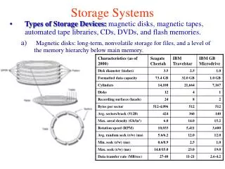
Content Ice storage and chilled water storage systems Typical ice storage and chilled water storage systems are as follows:- Ice storage Static Ice Production Systems Ice-on-coil, internal-melt ice storage system Ice-on-coil, external-melt ice storage system Encapsulated ice storage system Dynamic Ice Production Systems Ice-harvesting ice storage system Ice slurry system Chilled water storage Stratified chilled water storage system 2 2
ICE-ON-COIL, INTERNAL-MELT ICE STORAGE SYSTEM • Liquid coolant to absorb/ store heat energy in thermal storage systems • Brine is a salt solution or glycol solution • Used as a heat-transfer medium. • Freezing point < water (depends on the concentration of salt or glycol) • Consider ethylene glycol and propylene glycol for brine (both are colorless liquids). • Inhibitors must be added to ethylene and propylene glycols to prevent metal corrosion. • Brine is used as freezing point depressants to lower the freezing point of water • Freezing point : ethylene glycol solution at 25 percent by mass drops to -12.2°C • Freezing point : propylene glycol solution at 25 percent by mass drops to -9.4°C. • Therefore, ethylene glycol solution is preferred. • Ethylene glycol solution with 25-30% ethylene glycol circulates inside tubes at -4.4°C. 4 4
ICE-ON-COIL, INTERNAL-MELT ICE STORAGE SYSTEM ICE-ON-COIL, INTERNAL-MELT ICE STORAGE SYSTEM System - 1 Brine flowing inside coils to make ice and to melt ice in the water that surrounds the coil. 5
ICE-ON-COIL, INTERNAL-MELT ICE STORAGE SYSTEM A chilled water or brine-incorporated ice storage system consists of • Chillers, • Ice storage tanks, • Chiller pumps, • Building pumps, • Controls, • Piping, • AHUs • etc 6
ICE-ON-COIL, INTERNAL-MELT ICE STORAGE SYSTEM • Chillers • Centrifugal, screw, & reciprocating chillers • Selection based on the size of the plant and types of condenser (water-cooled, air cooled, or evaporative cool). • If daytime maximum temperature minus nighttime off-peak hours ≥ 12oC , air-cooled chillers more efficient than water-cooled ones. 7
ICE-ON-COIL, INTERNAL-MELT ICE STORAGE SYSTEM • Ice Storage Tank • Make use of many closely packed storage tanks connected in parallel => more flexible especially for retro-fit projects. • Ice is produced, or charged, in multiple storage tanks. • There are closely spaced multi-circuited polyethylene or plastic tubes surrounded by water. • Plastic tubes occupy about 1/10 of the tank volume. • Another 1/10 is left empty to accommodate the expansion of ice during ice making. 8
ICE-ON-COIL, INTERNAL-MELT ICE STORAGE SYSTEM Ice Storage Tank • The water surrounding the tubes freezes into ice up to a thickness of about 12.7 mm. • During ice burning, melted water separates the tube and ice. • Brine typically leaves the storage tank at -1.1°C. • Water has a thermal conductivity 0.61 W/m °C than much lower than ice 2.25 W/m °C=> capacity is dominated by the rate of ice burning. • During ice burning, brine returns from AHU at 7.8°C or higher. • This brine melts the ice on the outer surface of the tubes and is thus cooled to 1.1 to 2.2°C. 9
ICE-ON-COIL, INTERNAL-MELT ICE STORAGE SYSTEM Example :Demand-limited partial-storage strategy For summer cooling, the daily 24-h operating cycle can be divided into three periods: off-peak, direct cooling and on-peak. Off-peak: Ice is charged to reduce energy costs. On-peak: Ice is burned to reduce the demand charge. One chiller is operated. 10
ICE-ON-COIL, INTERNAL-MELT ICE STORAGE SYSTEM OFF-PEAK Ice making :Charge ice tanks 2) Direct cooling: Chiller(s) for nightload Ethylene glycol solution 1.1°C Tanks sensors : 100 percent charged => terminate ice-making 90 percent ice inventory => ice-making restart -6°C • Chiller Pump : High speed (ice making) • Higher flow rate • Pressure drop in evaporator & coils in ice storage tanks. Both Chillers Load limit = 100% 11
ICE-ON-COIL, INTERNAL-MELT ICE STORAGE SYSTEM DIRECT COOLING The start of AHUs & before peak period starts. Refrigeration load > both chillers’ capacity=> discharge from ice Direct cooling mode: Both chillers operates to supply chilled water. Chiller pumps at low speeds Direct cooling with ice-burning mode: Both chillers are turned on. Chiller pumps at low speeds 12
ICE-ON-COIL, INTERNAL-MELT ICE STORAGE SYSTEM ON-PEAK 1) Ice-burning : chiller at demand limit mode 2) Ice-burning without chiller mode 1.1°C Greater head : pressure drop of AHU & coil in ice tanks 0°C Chiller 1 or 2 lead/lag sequence. Load limit of chiller. 13 Both pumps during ice burning at low speed
ICE-ON-COIL, EXTERNAL-MELT ICE STORAGE SYSTEMS Theoldest type of ice storage system. Chillers, evaporating coils, storage tanks, condenser, heat exchanger, refrigerant pumps, chilled water pumps, air system controls, piping & fitting. Schematic diagram of ice-on-coil, external melt ice storage system 15
ICE-ON-COIL, EXTERNAL-MELT ICE STORAGE SYSTEMS Chilled Water Supply (CWS) Ice melts, => water supply at 1.1-3.3°C Refrigerant HCFC-22 is currently used.(HFC??) Compressor Capacity < 2400 ton h => reciprocating compressor Other capacity => Screw compressor Compressor suction temperature on ice building: -5.6 °C to -4.5°C Condenser Use evaporatively cooled condenser (a higher system energy efficiency ratio) 16
ICE-ON-COIL, EXTERNAL-MELT ICE STORAGE SYSTEMS Ice Builders Large, well-insulated steel tanks containing many serpentine (彎彎曲曲的) coils (steel pipes of 25-30mm diameter). Refrigerant-filled coils submerged in water and as evaporators. Ice builds up on outer surface of coils/tube banks : 25 - 64 mm thick Stored ice occupies only about ½ tank volume • Prevention of blockage in water circulation paths: • Good spacing of steel tubes to prevent the built-up of ice cylinders which bridge each other; • 2)Baffle plates to guide the water flow (which is also a secondary heat-transfer surface between refrigerant and water) 17
ICE-ON-COIL, EXTERNAL-MELT ICE STORAGE SYSTEMS Heat exchanger Reasons of use: Isolate storage tank brine system from the chilled water system connected to the AHUs. Because the chilled water system in a multistory building is always under a static head at lower levels Omission of storage tank: To supply chilled water directly to the storage tanks and pressurize the tanks.(a corresponding increase in brine temperature of about 1.7°C). Storage tank It contains refrigerant coils at a lower level or on grade because of weight. An electric probe senses water level in the tank to determine amount of ice stored in the tank.
ICE-ON-COIL, EXTERNAL-MELT ICE STORAGE SYSTEMS Refrigerant feed
ENCAPSULATED ICE STORAGE SYSTEMS An encapsulated ice storage system consists of: chillers, steel tank, encapsulated containers, pumps, air system controls, piping, and accessories. Charging: Secondary coolant is circulated through the tank. Discharging : Returned warm coolant from AHUs circulated through tank => ice melted. Direct cooling: Chillers => direct cooling at a coolant temperature from 2 to 6°C. 21
ENCAPSULATED ICE STORAGE SYSTEMS • Chillers and storage tanks are usually connected in series • When partial storage is used, two arrangements are possible: • 1) chiller upstream or • chiller downstream Chiller upstream Chiller downstream 22
ENCAPSULATED ICE STORAGE SYSTEMS Chilled water returned from AHUs at 8°C is first cooled in the chiller to 4°C, and then it enters the storage tank and is cooled down to 1°C. Advantage: Chilled water cooled at the chiller is at a higher temperature => a higher COP at the chiller. Disadvantage: Usable portion of the total storage capacity is reduced because of the lower storage tank discharge temperature 4°C 8°C 1°C Chiller upstream 23
ENCAPSULATED ICE STORAGE SYSTEMS Chilled water returned from AHU at 8°C is often first cooled in the storage tank to 4°C, and then it enters the chiller and is cooled down to 1°C. Disadvantage: COP of the chiller is lower, Advantage: The usable portion of the total storage capacity of the ice storage tanks is increased. 8°C 1°C 4°C Chiller downstream 24
ENCAPSULATED ICE STORAGE SYSTEMS • High-density polyethylene containers, filled with de-ionized water, are immersed in a secondary coolant (ethylene glycol solution) in a tank. • Two types of encapsulated ice containers : • Dimpled spheres of 100mm diameter • Rectangular containers :35x300x750 mm. • The Containers can withstand the pressure of expansion during freezing. • Containers are put or stacked in a way allowing free circulation of fluid and discouraging short-circuit of fluid flow 25
ENCAPSULATED ICE STORAGE SYSTEMS StorageTank - Open, non-pressurized type It needs a barrier to keep the frozen containers submerged into the coolant. Ice-charging inventory in the storage tank is measured based on the displacement of water in the tank when the ice is formed inside the encapsulated containers. A static pressure transducer is often used to detect the water level in the storage tank. Storage Tank- Pressurized type Expansion of the frozen containers forces the secondary coolant overflowing into a separate inventory tank, and its water level is measured. 26
ENCAPSULATED ICE STORAGE SYSTEMS Chiller priority control-chiller upstream. When the system refrigeration load is less than the chiller capacity, the chilled water bypasses the storage tanks completely(Pink line). When refrigeration load > the chiller capacity => chiller leaving temperature> set point, the control system diverts part of the chilled water flow through the storage tanks (blue line). Storage priority It requires refrigeration load prediction algorithm to forecast the chiller cooling needed each day. Increasing the chilled water leaving setpoint to limit the chiller capacity Most of or all the refrigeration load is by ice storage. Chiller upstream 27
ICE-HARVESTING ICE STORAGE SYSTEMS An ice-harvesting ice storage system consists of: chillers, an ice harvester, storage tank, air system controls, piping, and accessories. 29
ICE-HARVESTING ICE STORAGE SYSTEMS Equipment Ice is produced in a harvester, which is separate from the storage tank where ice is stored. The evaporator of the chiller is a vertical plate heat exchanger mounted above a water / ice storage tank. Low-pressure liquid refrigerant is forced through the inner part of the plate heat exchanger is vaporized => refrigeration effect. 30
ICE-HARVESTING ICE STORAGE SYSTEMS Ice Making or Charging A chilled aqueous is : pumped from the storage tank. is distributed over the outer surface of the evaporator plates at a temperature equal to or slightly above 0oC. flows downward along the outer surface of the plate in a thin film. Water is cooled and then frozen into ice sheets approximately 5 to 7.5 mm thick. Ice is formed in 20 to 30 min. 31
ICE-HARVESTING ICE STORAGE SYSTEMS Iceharvesting Ice is harvested,in the form of flakes or chunks and falls into the storage tank below. Periodically, hot gas is introduced into 1/4 evaporatorplates by reversing the refrigerant flow. Ice is harvested within 20 to 40s (plate evaporator acts as condenser). Ice accumulates about 60 percent of storage tank volume. The ice flakes are around 150 mm by 150 mm by 6 mm But melting of the ice during the harvesting process decreases the amount of ice harvested and adds an incremental refrigeration load to the system. 32
ICE-HARVESTING ICE STORAGE SYSTEMS Other considerations Successfully used in load shifting and load leveling to reduce electric demand and energy cost. It is an open system. More water treatment is required than in an ice-on-coil, internal-melt ice storage system Evaporator plates must be located above the storage tank, ice-harvesting systems need more headroom 33
SLURRY ICE SYSTEM Slurry ice It is a suspension of very small ice crystals in a liquid. The binary ice fluid contains latent energy in the form of ice minute crystals (sizes various from 1/10 – 1/100 mm) It changes from the frozen state to the liquid state when heat is absorbed. This phase change is instantaneous (much faster than normal ice melting). The slurry liquid is pumpable.
SLURRY ICE SYSTEM Slurry ice • The working fluid’s liquid state consists of a solvent (water) and a solute such as glycol, ethanol, or calcium carbonate. • The initial solute concentration varies from 2% to over 10% by mass. • The solute depresses the freezing point of the solvent. • The freezing point of an aqueous solutions calcium magnesium acetate decrease with increase in concentrations. • The fraction of ice in a given system can be estimated by knowing : • The initial solute concentration and • The freezing point characteristic of the working fluid. 8% calcium magnesium acetate
SLURRY ICE SYSTEM Advantages of Slurry ice storage system The Slurry-Ice system is a dynamic type ice storage system which offers the pumpable characteristic advantage over any other type of dynamic systems. and the icy slurry can be pumped Slurry-Ice is a very versatile cooling medium: The handling characteristics, and cooling capacities can match any application by adjusting the percentage of ice concentration. Slurry-Ice does not suffer from the static type disadvantages of ice bridging and ice insulation effects. Slurry-Ice instantly melts to meet varying cooling load. Hence, ensuring steady and accurate system leaving temperature control. 37
SLURRY ICE SYSTEM Comparison on cooling capacity Conventional chilled water systems The enthalphy difference of water between 6 and 12oC => a cooling capacity of 30 kJ/kg. Slurry ice Cooling System The latent heat carried by ice particles in the water adds great cooling capacity to the flow. The cooling capacity of slurry ice operation at 0/13 oC with ice fraction of 20% equals to 144 kJ/kg. The use of slurry ice significantly decreases the volumetric flow requirements.
SLURRY ICE SYSTEM Compressor/Condenser It supplies refrigerant to the evaporator. IceSlurry Generator (evaporator) Water & freeze depressant mixture to produce a pumpable ice slurry. Options of Generators are as follows: - Supercooled Slurry Ice Generator Scraper Type Slurry Generator Ejector System Vacuum Type Slurry Ice Generator Falling Film Type Slurry Ice Machine
SLURRY ICE SYSTEM Falling Film Type Slurry Ice Machine The internal falling film process is based on supercooling the solution which is disturbed by a spinning rod in order to overcome the formation of solid ice and prevent it sticking to the inner surface of the pipe. Once the solution is supercooled and disturbed, it forms microscopic fine binary ice crystals which are collected at the bottom of the vessel. The ice concentration and capacity control can be adjusted by either controlling suction pressure, solution flow rates or both. Low friction between the rod and the tube wall and the slurry ice solution acts like a lubricant.
SLURRY ICE SYSTEM Insulated Ice Storage Tank It separates ice manufacturing from ice usage. The tank contains a glycol/water solution which is converted to an ice slurry in the ice slurry generator. The slurry melts as the stored ice absorbs the heat of the cooling load.
SLURRY ICE SYSTEM Plate Heat Exchanger It separates the storage tank from cooling equipment. It prevents cross contamination between the ice- melting loop & cooling equipment. Heat Exchangers - Variation of Heat Transfer Co-efficient with Ice Fraction. An increasing ice fraction reduces the overall heat transfer co-efficient. A 17-20% reduction in the heat transfer co-efficient can be expected when the ice fraction was increased from 0 % to 15%. This reduction can be explained by the fact that slurry ice reduces turbulence in the liquid.
SLURRY ICE SYSTEM Load Control Pump and Valve For provide the flow and control the supply temperature to the load. A minimum velocity must be maintained for ice fractions between 0.1 and 0.25. Below this velocity=> the pressure gradient increases when the velocity is decreased=> Phase separation, with ice floating to the top of the pipe, causes the effective liquid flow cross-section to decrease. A number of pressure drop experiments conducted at slurry ice velocities over 3m/s and ice fractions in excess of 20% in straight tubes with internal diameters of 25, 51 and 76 mm indicate no difference in pressure gradient between water and slurry ice. At at slurry ice velocities < 1 m/s, the loop pressure drop was slightly above the pressure drop of the water.
STRATIFIED CHILLED WATER STORAGE SYSTEMS A large storage tank to store chilled water (4-7oC). To shift the load to the off-peak hours and reduces the energy cost. The chilled water incorporated storage system consist of Chillers, A cylindrical storage tank, Pumps, Piping, Accessories etc Chilled Water Storage System
STRATIFIED CHILLED WATER STORAGE SYSTEMS Chilled water in the storage tank is stratified into three regions The stored cooling capacity depends 1)Temperature difference between water return from AHUs and stored chilled water 2) Amount of water stored. The larger the storage tank, the lower the capital cost per unit stored volume. It was found that a chilled water storage system is economical for large capacity (storage capacity exceeds 7000 kWh). 47
STRATIFIED CHILLED WATER STORAGE SYSTEMS • Charging • Filling the storage tank with chilled water from the chiller • The warmer return chilled water from AHU is extracted from the storage tank and pumped to the chiller 11-16oC 4-7oC 48
STRATIFIED CHILLED WATER STORAGE SYSTEMS Discharging Chilled water from the storage tank is supplied to the terminal units such as air handling units. At the same time, the warmer return chilled water from the coils fills the tank with an aid of storage water pumps. 5-7oC,
STRATIFIED CHILLED WATER STORAGE SYSTEMS Figure of merit(FOM) It is used to indicate the loss of cooling capacity of the stored chilled water during the charging and discharging processes. 50