Download
1 / 26
290 likes | 547 Views
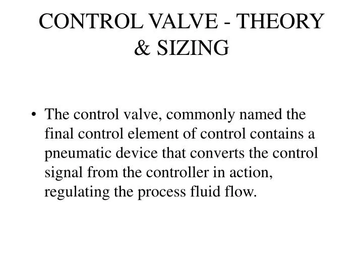
CONTROL VALVE - THEORY & SIZING. The control valve, commonly named the final control element of control contains a pneumatic device that converts the control signal from the controller in action, regulating the process fluid flow.

E N D
CONTROL VALVE - THEORY & SIZING • The control valve, commonly named the final control element of control contains a pneumatic device that converts the control signal from the controller in action, regulating the process fluid flow.
. Valves make up approximately 15% of the total expenditure for the materials and equipments for the refinery or chemical processing industry. . Valves are used to handle variety of liquids , gases , steam, air etc.
SPECIFICATION OF VALVES- • Flow medium • Flow : kg/hr or Nm3/hr Max/Min/Normal • Inlet pressure : kg/cm2 Max/Min/Normal • Outlet pressure:kg/cm2 Max/Min/Normal • Max. allowable diff. Pressure : kg/cm2 • Density of medium : kg/m3 • Viscosity
SPECIFICATION OF VALVES- • Operating temperature - Deg. C • Design Pressure / temp. • End connection • MOC desired • leak Tightness required • Actuator : Pneumatic / electrical • Max. compressed air available : kg/cm2 • Cv :
CATEGORY OF VALVES • ON - OFF SERVICES :- Gate, Ball, Diaphragm, Plug, Butterfly valves. • THROTTLING SERVICES :- Globe, Butterfly, Diaphragm, Pinch valves. • NON - REVERSE FLOW :- Check valves.
GATE VALVES - • The Gate Valves are characterized by a sliding gate which is moved by the stem perpendicular to the direction of flow. • Application :- It is used for on-off application. Suited for high temperature and pressure use with variety of fluids. They are not primarilly used for slurries, viscous fluid etc.
ADVANTAGES : Low pressure drop when fully open and tight sealing DISADVANTAGES: Causes Vibration, seat disc wear in partial open condition. Slow response characteristic and require large actuating force. GATE VALVES -
GLOBE VALVES - • In Globe Valves disc or plug is moved on and off the seat.The seat opening is directly proportional to the travel of the disc.It is short stem travel, high seating capacity, large pressure drop & high flow controllability. • Application :- It is used primarily for throttling purposes. It may be considered a general purpose flow control valve. Specifically very widely used for high temp. application.
GLOBE VALVES - • ADVANTAGES : Faster to open or close, most reliable form of seating, throttling to control the flow to any desired degree, positive shut-off • DISADVANTAGES: Seat disc wear in partial open condition.
PLUG VALVES - • It consist of body, plug and cover. The plug is tapered or cylindrical. In the open position, the bore in the plug connects the inlet and outlet ends of the valve providing straight line flow. • Application :- The plug valves are extensively used in refinery, petrochem and chemical industries and for general purpose involving on off services.
PLUG VALVES - • ADVANTAGES : Normally small in size, require less headroom and available in wide range of materials. They provide tight shut off, quick opening and low pressure drop. • DISADVANTAGES: Plug valve may be subjected to galling.
BALL VALVES - • It is improvisation of the plug valve. It is basically a ported sphere in a housing.The seat matching the ball is circulars so that the seating stress is circumferentially uniform. The seats are usually made up of PTFE which is inert to all chemicals, has low coefficient of friction and resiliency. • Application :- It is used for flow & pressure control and shut off and for corrosive fluids, slurries, normal liquid & gases. For high temp. & pressure
BALL VALVES - • ADVANTAGES : Low pressure drop, tight shut off, quarter turn operation, easy to maintain, low torque. They are small in size and low in weight. • DISADVANTAGES: PTFE seats are subjected to extrusion if the valve is used for throttling. Fluid trapped in the ball in the closed position may cause problem of build up of vapour pressure & corrosion.
BUTTERFLY VALVES - • They are rotary valves with a disc rotating at right angles within a pipe section body. • The stem passes through this disc and is supported by both ends of the body. • The shaft is ensured to the disc either by bolts or pins. Rotating the stem through 90 degs. Fully opens or closes the valves. • Application :- Low pressure application where leakage is unimportant.
BUTTERFLY VALVES - • ADVANTAGES : Simple , compact form, quick opening, good controllability, low pressure drop and low weights and costs. • DISADVANTAGES: No tight shut off.
DIAPHRAGM VALVES - • The flexible diaphragm is connected to a support member known as compressor, which represent the closure member. When the valve is opened the diaphragm is lifted out of the flow path and the fluid has a smooth streamlined flow. When the valve is closed the diaphragm is tightly seated against the seta in the body known as the weir. The diaphragm is of PTFE. • Application :- Used for corrosive liquids at low temp. and pressure.
DIAPHRAGM VALVES - • ADVANTAGES : The diaphragm completely keeps the working parts in isolation from the process fluids. Simple in construction, easier to operate and maintain. • DISADVANTAGES: Not for high temp. and pressure.
CONTROL VALVE - PRINCIPAL OF OPERATION • It is based upon balanced forces between pneumatic force from the diaphragm against a mechanical force produced by the actuator spring.The control valve works with a pneumatic signal 3 to 15 psi. The motion starts at 3 psi and ends at 15 psi.
COMPONENT OF CONTROL VALVE • Actuator • Body • Trim • Diaphragm • Diaphragm plate • Actuator stem • Actuator spring • Seat
COMPONENT OF CONTROL VALVE • Travel Indicator • Valve stem • Gaskests • Yoke • Handwheel
TERMINOLOGY • Flow Co-efficients (Cv) :- The flow of water (G=1, T= 6 to 34 deg. C) through the valve at full lift in U.S gallon per minute with a pressure drop across the valve of 1 psi.
CHARACTERISTIC CURVES QUICK OPENING FLOW % LINEAR EQUAL % VALVE LIFT %
Linear :-Flow is directly proportional to lift. • Equal Percentage :- Flow changes by a constant percentage of its instantaneous values for each unit change in lift. • Quick Opening :- Flow increases rapidly in a linear relationship with plug lift reaching a max. value at a low lift.