Download
1 / 17
170 likes | 292 Views
Vertical-flexure CCD module: Thermal and Dynamic FEA. Bruce C. Bigelow University of Michigan Department of Physics 10/28/04. Vertical-flexure CCD module. Objectives: Accommodate Moly-Invar CTE mismatch with vertical flexure Moly CCD mount (see previous presentation)

E N D
Vertical-flexure CCD module:Thermal and Dynamic FEA Bruce C. Bigelow University of Michigan Department of Physics 10/28/04
Vertical-flexure CCD module Objectives: • Accommodate Moly-Invar CTE mismatch with vertical flexure Moly CCD mount (see previous presentation) • Demonstrate acceptable thermal stresses for package over survival temperature range • Demonstrate acceptable modal performance for package
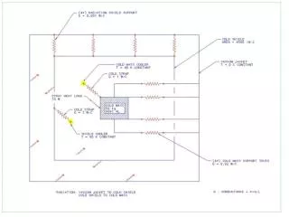
Vertical-flexure module FEA Analyses: • Neglect AlN, silicon from models (TZM and Invar only) • No pre-stress of package at room temp • TZM Flexure geometry (not optimized): • Blade thickness = 0.4 mm (0.016”) • Blade width = 8 mm (0.32”) • Blade effective length = 4 mm (0.16”) • Thermal: • Simple delta-T = -160K, constant CTEs • Frame constrained for zero mounting stress • Dynamic: • Mounting pads constrained • TZM Flexure to Invar joint nodes coupled
Vertical-flexure module FEA Analyses: • Thermal: • Simple DT = -160K, constant CTEs • Frame constrained for zero base stress at mounting • Flexures and Invar base interface nodal deflections coupled at centerline to simulate single screw constraints (very conservative – neglects screw head constraint) • Z constraints coupled at top of Invar surface (worst case)
CCD module FEA – frame stress Max stress in flexures – 132 MPa – 19,410 PSI (TZM Sy = 860 MPa)
CCD module FEA – Invar stress Max stress in Invar – 5.6 MPa – 812 PSI (Invar Sy = 300 MPa)
CCD module FEA - elements Max distortion of Invar base (CCD mounting surface) is 0.1 micron
Vertical-flexure module FEA Analyses: • Dynamic: • Modal analysis, reduced (Householder) modal extraction • TZM - Invar interface nodal deflections coupled as in thermal case • First 10 frequencies: • SET TIME/FREQ • 1 3279.8 • 2 3458.6 • 3 3955.8 • 4 5009.2 • 5 6928.7 • 6 7684.2 • 7 8830.7 • 8 9707.0 • 9 12753. • 10 13239.
Vertical flexure CCD module Conclusions: • Thermal and dynamic FEA presented • Low thermal stresses demonstrated with non-optimized TZM flexures • High resonant frequencies demonstrated with non-optimized TZM flexures • Optimal flexure dimensions still TBD for minimal stress and maximum first resonance