Download
1 / 46
460 likes | 570 Views
Internet Protocol. ECS 152A Xin Liu. Ref: slides by J. Kurose and K. Ross. Goals. Principles of network layer services Internet Protocol Addressing Routing ICMP. Overview. Encapsulation. application message. User process. User process. HTTP. SNMP. TCP. UDP. transport segment.

E N D
Internet Protocol ECS 152A Xin Liu Ref: slides by J. Kurose and K. Ross
Goals • Principles of network layer services • Internet Protocol • Addressing • Routing • ICMP
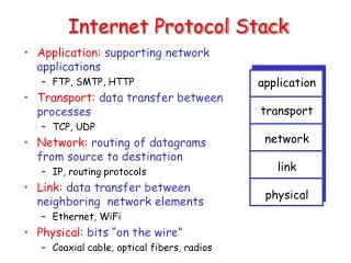
Overview Encapsulation application message User process User process HTTP SNMP TCP UDP transport segment network datagram ICMP IP Hardware interface link frame ARP RARP Demultiplexing
transport packet from sending to receiving hosts network layer protocols in every host, router network data link physical network data link physical network data link physical network data link physical network data link physical network data link physical network data link physical network data link physical application transport network data link physical application transport network data link physical Network layer functions
Functions • path determination: route taken by packets from source to dest. Routing algorithms • forwarding: move packets from router’s input to appropriate router output • call setup: some network architectures require router call setup along path before data flows (not Internet)
Q:What service model for transporting packets from sender to receiver? guaranteed bandwidth? preservation of inter-packet timing (no jitter)? loss-free delivery? in-order delivery? congestion feedback to sender? Network service model The most important abstraction provided by network layer: ? ? virtual circuit or datagram? service abstraction ?
call setup, teardown for each call before data can flow each packet carries VC identifier (not destination host ID) every router on source-dest path maintains “state” for each passing connection link, router resources (bandwidth, buffers) may be allocated to VC to get circuit-like perf. “source-to-dest path behaves much like telephone circuit” Virtual circuits
used to setup, maintain teardown VC used in ATM, frame-relay, X.25 not used in today’s Internet application transport network data link physical application transport network data link physical Virtual circuits: signaling protocols 6. Receive data 5. Data flow begins 4. Call connected 3. Accept call 1. Initiate call 2. incoming call
no call setup at network layer routers: no state about end-to-end connections no network-level concept of “connection” packets forwarded using destination host address packets between same source-dest pair may take different paths application transport network data link physical application transport network data link physical Datagram networks: the Internet model 1. Send data 2. Receive data
VC vs. Datagram • VC • Guaranteed service • Complexity • Datagram • Simple • Best effort
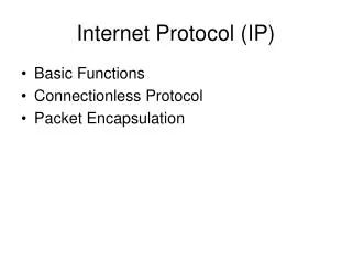
Internet Protocol • Functionality: • Determine how to route packets from source to destination • Hide the details of the physical network • Unreliable, connectionless, datagram delivery • To be mentioned: • Addressing • Routing • ICMP
Encapsulation source destination original message Application Application Transport Transport Network Network Link Link
IP protocol version number 32 bits total datagram length (bytes) header length (bytes) type of service head. len ver length for fragmentation/ reassembly fragment offset “type” of data flgs 16-bit identifier max number remaining hops (decremented at each router) upper layer time to live header checksum 32 bit source IP address 32 bit destination IP address upper layer protocol to deliver payload to E.g. timestamp, record route taken, specify list of routers to visit. Options (if any) data (variable length, typically a TCP or UDP segment) IP header 20 bytes overhead
IP Header • Version: 4 • Header length: 4 bits, max 15x4=60 bytes • TOS: 0 for normal service, • Total length: 16 bits, max 65535 bytes • TTL: 32/64, decrease by one in each hop • Protocol field: TCP,UCP,ICMP,IGMP,etc. • Checksum: header only
class 1.0.0.0 to 127.255.255.255 A network 0 host 128.0.0.0 to 191.255.255.255 B network 10 host 192.0.0.0 to 223.255.255.255 C network host 110 224.0.0.0 to 239.255.255.255 D multicast address 1110 32 bits IP Address Class-based address: 7 bits 14 bits 21 bits 28 bits
host part network part 11001000 0001011100010000 00000000 200.23.16.0/23 IP addressing: CIDR • Classful addressing: • inefficient use of address space, address space exhaustion • e.g., class B net allocated enough addresses for 65K hosts, even if only 500 hosts in that network • CIDR:Classless InterDomain Routing • network portion of address of arbitrary length • address format: a.b.c.d/x, where x is # bits in network portion of address
CIDR • Network address: 200.23.16.0/23 • /23 : network mask • More efficient use of address • Consider a network with 500 hosts • Classful address: a class B address, wasting over 64K addresses • CIDR: a network with /23 • One class B address can be used for 128 such networks using CIDR • Routing difficulty • Classful: only need the IP address to determine the network add • CIDR: also need network mask information to determine the network address • Longest match first
IP address: 32-bit identifier for host, router interface interface: connection between host/router and physical link router’s typically have multiple interfaces host may have multiple interfaces IP addresses associated with each interface 223.1.1.2 223.1.2.1 223.1.3.27 223.1.3.1 223.1.3.2 223.1.2.2 IP routing 223.1.1.1 223.1.2.9 223.1.1.4 223.1.1.3 223.1.1.1 = 11011111 00000001 00000001 00000001 223 1 1 1 Network address: 223.1.1.0/24
IP address: network part (high order bits) is used for routing host part (low order bits) not used for routing IP Routing 223.1.1.1 223.1.2.1 223.1.1.2 223.1.2.9 223.1.1.4 223.1.2.2 223.1.1.3 223.1.3.27 LAN 223.1.3.2 223.1.3.1 network consisting of 3 IP networks (for IP addresses starting with 223, first 24 bits are network address)
IP datagram: A E B source IP addr misc fields dest IP addr data 223.1.1.1 223.1.2.1 223.1.1.2 223.1.2.9 223.1.1.4 223.1.2.2 223.1.1.3 223.1.3.27 Dest. Net. next router Nhops 223.1.1 1 223.1.3.2 223.1.3.1 223.1.2 223.1.1.4 2 223.1.3 223.1.1.4 2 Others 223.1.1.4 x Getting a datagram from source to dest. forwarding table in A • datagram remains unchanged, as it travels source to destination • addr fields of interest here • Default router for all other networks
B E A 223.1.1.1 223.1.2.1 223.1.1.2 223.1.2.9 223.1.1.4 223.1.2.2 223.1.1.3 223.1.3.27 Dest. Net. next router Nhops 223.1.1 1 223.1.3.2 223.1.3.1 223.1.2 223.1.1.4 2 223.1.3 223.1.1.4 2 Getting a datagram from source to dest. forwarding table in A misc fields data 223.1.1.1 223.1.1.3 Starting at A, send IP datagram addressed to B: • look up net. address of B in forwarding table • find B is on same net. as A • link layer will send datagram directly to B inside link-layer frame • B and A are directly connected
E A B 223.1.1.1 223.1.2.1 223.1.1.2 223.1.2.9 223.1.1.4 223.1.2.2 223.1.1.3 223.1.3.27 Dest. Net. next router Nhops 223.1.1 1 223.1.3.2 223.1.3.1 223.1.2 223.1.1.4 2 223.1.3 223.1.1.4 2 Getting a datagram from source to dest. forwarding table in A misc fields data 223.1.1.1 223.1.2.3 Starting at A, dest. E: • look up network address of E in forwarding table • E on different network • A, E not directly attached • routing table: next hop router to E is 223.1.1.4 • link layer sends datagram to router 223.1.1.4 inside link-layer frame • datagram arrives at 223.1.1.4 • continued…..
Dest. Net router Nhops interface B A E 223.1.1 - 1 223.1.1.4 223.1.2 - 1 223.1.2.9 223.1.3 - 1 223.1.3.27 223.1.1.1 223.1.2.1 223.1.1.2 223.1.2.9 223.1.1.4 223.1.2.2 223.1.1.3 223.1.3.27 223.1.3.2 223.1.3.1 Getting a datagram from source to dest. forwarding table in router misc fields data 223.1.1.1 223.1.2.3 Arriving at 223.1.4, destined for 223.1.2.2 • look up network address of E in router’s forwarding table • E on same network as router’s interface 223.1.2.9 • router, E directly attached • link layer sends datagram to 223.1.2.2 inside link-layer frame via interface 223.1.2.9 • datagram arrives at 223.1.2.2!!! (hooray!)
host part network part 11001000 0001011100010000 00000000 200.23.16.0/23 CIDR Routing host part network part 11001000 0001011100000000 00000000 200.23.0.0/17 CIDR routing: longest match first
network links have MTU (max.transfer size) - largest possible link-level frame. different link types, different MTUs large IP datagram divided (“fragmented”) within net one datagram becomes several datagrams “reassembled” only at final destination IP header bits used to identify, order related fragments IP Fragmentation & Reassembly fragmentation: in: one large datagram out: 3 smaller datagrams reassembly
length =1500 length =1500 length =4000 length =1040 ID =x ID =x ID =x ID =x fragflag =0 fragflag =1 fragflag =0 fragflag =1 offset =0 offset =0 offset =1480 offset =2960 One large datagram becomes several smaller datagrams IP Fragmentation and Reassembly Example • 4000 byte datagram • MTU = 1500 bytes
IPv6 • Initial motivation:32-bit address space completely allocated by 2008. • Additional motivation: • header format helps speed processing/forwarding • header changes to facilitate QoS • new “anycast” address: route to “best” of several replicated servers • IPv6 datagram format: • fixed-length 40 byte header • no fragmentation allowed
IPv6 Header (Cont) Priority: identify priority among datagrams in flow Flow Label: identify datagrams in same “flow.” (concept of“flow” not well defined). Next header: identify upper layer protocol for data
Other Changes from IPv4 • Checksum:removed entirely to reduce processing time at each hop • Options: allowed, but outside of header, indicated by “Next Header” field • ICMPv6: new version of ICMP • additional message types, e.g. “Packet Too Big” • multicast group management functions
Transition From IPv4 To IPv6 • Not all routers can be upgraded simultaneous • no “flag days” • How will the network operate with mixed IPv4 and IPv6 routers? • Two proposed approaches: • Dual Stack: some routers with dual stack (v6, v4) can “translate” between formats • Tunneling: IPv6 carried as payload in IPv4 datagram among IPv4 routers
Flow: ?? Src: A Dest: F data Flow: X Src: A Dest: F data D A B E F C Src:A Dest: F data Src:A Dest: F data Dual Stack Approach IPv6 IPv6 IPv6 IPv6 IPv4 IPv4 A-to-B: IPv6 B-to-C: IPv4 B-to-C: IPv6 B-to-C: IPv4
Flow: X Src: A Dest: F data Flow: X Src: A Dest: F data Flow: X Src: A Dest: F data Flow: X Src: A Dest: F data D C F E B A F E B A Src:B Dest: E Src:B Dest: E Tunneling tunnel Logical view: IPv6 IPv6 IPv6 IPv6 Physical view: IPv6 IPv6 IPv6 IPv6 IPv4 IPv4 A-to-B: IPv6 E-to-F: IPv6 B-to-C: IPv6 inside IPv4 B-to-C: IPv6 inside IPv4
ICMP (Internet Control Message Protocol) TypeCode description Query Error 0 0 echo reply (ping) x 3 0 dest. network unreachable x 3 1 dest host unreachable x 3 2 dest protocol unreachable x 3 3 dest port unreachable x 3 6 dest network unknown x 3 7 dest host unknown x 4 0 source quench (congestion x control - not used) 8 0 echo request (ping) x 9 0 route advertisement x 10 0 router discovery x 11 0 TTL expired x 12 0 bad IP header x
8-bit code 16-bit checksum 8-bit type Contents depends on type and code ICMP IP datagram IP header ICMP message
Error message • ICMP error message: • ICMP header: • type, code, checksum, • ICMP message • IP header plus first 8 bytes of IP datagram causing error • To prevent broadcast storm: NOT generate ICMP in response to • ICMP error message • Dest=IP broadcast address • Link layer broadcast • A fragment other than the first • Source address not defined as a single host
Ping • Basic connectivity test • uses ICMP eco request/reply messages instead of UDP/TCP. • Client/server paradigm • Usually implemented in the kernel. • “man ping”
code(0) 16-bit checksum type (0) Optional data Format sequence no. identifier
Ping bread% ping -s shannon.cs.ucdavis.edu PING shannon.cs.ucdavis.edu: 56 data bytes 64 bytes from shannon.cs.ucdavis.edu (169.237.6.199): icmp_seq=0. time=0. ms 64 bytes from shannon.cs.ucdavis.edu (169.237.6.199): icmp_seq=1. time=0. ms 64 bytes from shannon.cs.ucdavis.edu (169.237.6.199): icmp_seq=2. time=0. ms 64 bytes from shannon.cs.ucdavis.edu (169.237.6.199): icmp_seq=3. time=0. ms 64 bytes from shannon.cs.ucdavis.edu (169.237.6.199): icmp_seq=4. time=0. ms 64 bytes from shannon.cs.ucdavis.edu (169.237.6.199): icmp_seq=5. time=0. ms 64 bytes from shannon.cs.ucdavis.edu (169.237.6.199): icmp_seq=6. time=0. ms 64 bytes from shannon.cs.ucdavis.edu (169.237.6.199): icmp_seq=7. time=0. ms 64 bytes from shannon.cs.ucdavis.edu (169.237.6.199): icmp_seq=8. time=0. ms 64 bytes from shannon.cs.ucdavis.edu (169.237.6.199): icmp_seq=9. time=0. ms … ----shannon.cs.ucdavis.edu PING Statistics---- 30 packets transmitted, 30 packets received, 0% packet loss round-trip (ms) min/avg/max = 0/0/0
Ping bread% ping -s mark.ecn.purdue.edu PING mark.ecn.purdue.edu: 56 data bytes 64 bytes from mark.ecn.purdue.edu (128.46.209.167): icmp_seq=0. time=66. ms 64 bytes from mark.ecn.purdue.edu (128.46.209.167): icmp_seq=1. time=64. ms 64 bytes from mark.ecn.purdue.edu (128.46.209.167): icmp_seq=3. time=64. ms 64 bytes from mark.ecn.purdue.edu (128.46.209.167): icmp_seq=4. time=65. ms 64 bytes from mark.ecn.purdue.edu (128.46.209.167): icmp_seq=5. time=64. ms 64 bytes from mark.ecn.purdue.edu (128.46.209.167): icmp_seq=8. time=65. ms 64 bytes from mark.ecn.purdue.edu (128.46.209.167): icmp_seq=10. time=65. ms 64 bytes from mark.ecn.purdue.edu (128.46.209.167): icmp_seq=11. time=65. ms 64 bytes from mark.ecn.purdue.edu (128.46.209.167): icmp_seq=12. time=65. ms 64 bytes from mark.ecn.purdue.edu (128.46.209.167): icmp_seq=15. time=64. ms ^C ----mark.ecn.purdue.edu PING Statistics---- 18 packets transmitted, 10 packets received, 44% packet loss round-trip (ms) min/avg/max = 64/65/66
Traceroute • By Van Jacobson • See route that IP datagram follow • Use ICMP and TTL • A router gets an IP datagram with TTL 0/1, discards the packet and sends back an ICMP to the source “time exceeded”. • Source sends UDP fragment with 1,2,3, TTL values • IP packet contains an UDP with unused post #. dest. Replies “port unreachable” ICMP message.
Traceroute bread% traceroute ector.cs.purdue.edu traceroute: Warning: Multiple interfaces found; using 169.237.6.16 @ qfe0 traceroute to ector.cs.purdue.edu (128.10.2.10), 30 hops max, 40 byte packets 1 169.237.5.254 (169.237.5.254) 0.594 ms 0.337 ms 0.298 ms 2 169.237.246.238 (169.237.246.238) 0.533 ms 0.479 ms 0.474 ms 3 128.120.2.49 (128.120.2.49) 0.547 ms 0.475 ms 0.475 ms 4 core0.ucdavis.edu (128.120.0.30) 0.616 ms 0.671 ms 0.642 ms 5 area0-area14p.ucdavis.edu (128.120.0.222) 0.570 ms 0.468 ms 0.821 ms 6 area14p-border20.ucdavis.edu (128.120.0.250) 1.149 ms 0.691 ms 3.132 ms 7 dc-oak-dc2--ucd-ge.cenic.net (137.164.24.225) 4.751 ms 2.434 ms 4.521 ms 8 dc-oak-dc1--oak-dc2-ge.cenic.net (137.164.22.36) 2.394 ms 4.217 ms 2.452 ms 9 dc-svl-dc1--oak-dc1-10ge.cenic.net (137.164.22.30) 201.245 ms 5.091 ms 183.393 ms 10 dc-sol-dc1--svl-dc1-pos.cenic.net (137.164.22.28) 13.421 ms 11.258 ms 11.155 ms 11 hpr-lax-hrp1--dc-lax-dc1-ge.cenic.net (137.164.22.13) 11.571 ms 14.390 ms 11.809 ms 12 abilene-LA--hpr-lax-gsr1-10ge.cenic.net (137.164.25.3) 13.431 ms 11.417 ms 11.289 ms 13 snvang-losang.abilene.ucaid.edu (198.32.8.95) 19.141 ms 20.516 ms 19.117 ms 14 kscyng-snvang.abilene.ucaid.edu (198.32.8.103) 54.300 ms 53.943 ms 53.998 ms 15 iplsng-kscyng.abilene.ucaid.edu (198.32.8.80) 64.783 ms 68.220 ms 63.659 ms 16 ul-abilene.indiana.gigapop.net (192.12.206.250) 63.567 ms 63.381 ms 63.025 ms 17 tel-210-m10-01-gp.tcom.purdue.edu (192.5.40.9) 65.017 ms * 64.982 ms 18 cs-2u01-c3550-01-242.tcom.purdue.edu (128.210.242.51) 65.527 ms 65.282 ms 65.083 ms 19 * ector.cs.purdue.edu (128.10.2.10) 65.528 ms *
NAT: Network Address Translation rest of Internet local network (e.g., home network) 10.0.0/24 10.0.0.1 10.0.0.4 10.0.0.2 138.76.29.7 10.0.0.3 Datagrams with source or destination in this network have 10.0.0/24 address for source, destination (as usual) All datagrams leaving local network have same single source NAT IP address: 138.76.29.7, different source port numbers
NAT: Network Address Translation • Motivation: local network uses just one IP address as far as outside word is concerned: • no need to be allocated range of addresses from ISP: - just one IP address is used for all devices • can change addresses of devices in local network without notifying outside world • can change ISP without changing addresses of devices in local network • devices inside local net not explicitly addressable, visible by outside world (a security plus).
NAT: Network Address Translation Implementation: NAT router must: • outgoing datagrams:replace (source IP address, port #) of every outgoing datagram to (NAT IP address, new port #) . . . remote clients/servers will respond using (NAT IP address, new port #) as destination addr. • remember (in NAT translation table) every (source IP address, port #) to (NAT IP address, new port #) translation pair • incoming datagrams:replace (NAT IP address, new port #) in dest fields of every incoming datagram with corresponding (source IP address, port #) stored in NAT table
3 1 2 4 S: 10.0.0.1, 3345 D: 128.119.40.186, 80 S: 138.76.29.7, 5001 D: 128.119.40.186, 80 1: host 10.0.0.1 sends datagram to 128.119.40, 80 2: NAT router changes datagram source addr from 10.0.0.1, 3345 to 138.76.29.7, 5001, updates table S: 128.119.40.186, 80 D: 10.0.0.1, 3345 S: 128.119.40.186, 80 D: 138.76.29.7, 5001 NAT: Network Address Translation NAT translation table WAN side addr LAN side addr 138.76.29.7, 5001 10.0.0.1, 3345 …… …… 10.0.0.1 10.0.0.4 10.0.0.2 138.76.29.7 10.0.0.3 4: NAT router changes datagram dest addr from 138.76.29.7, 5001 to 10.0.0.1, 3345 3: Reply arrives dest. address: 138.76.29.7, 5001
NAT: Network Address Translation • 16-bit port-number field: • 60,000 simultaneous connections with a single LAN-side address! • NAT is controversial: • routers should only process up to layer 3 • violates end-to-end argument • NAT possibility must be taken into account by app designers, eg, P2P applications • address shortage should instead be solved by IPv6