Download
1 / 24
240 likes | 367 Views
Japan-US Workshop on Fusion Power Plants Related Advanced Technologies with participants from China and Korea ( Kyoto University, Uji , Japan, 26-28 Feb. 2013 ). Core Plasma Design for FFHR-d1 and c1. J. Miyazawa , M. Yokoyama, Y . Suzuki, S. Satake, R. Seki,

E N D
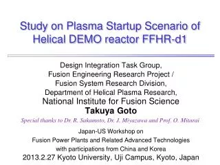
Japan-US Workshop on Fusion Power Plants Related Advanced Technologies with participants from China and Korea (Kyoto University, Uji, Japan, 26-28 Feb. 2013) Core Plasma Design for FFHR-d1 and c1 J. Miyazawa, M. Yokoyama, Y. Suzuki, S. Satake, R. Seki, Y. Masaoka1, S. Murakami1, T. Goto, A. Sagara, and the FFHR Design Group National Institute for Fusion Science 1)Kyoto University
Outline • FFHR-d1 - concept and specifications • DPE (Direct Profile Extrapolation) method - basic equations • Detailed physics analysis - FFHR-d1 is a semi-optimal Heliotron - new reference profiles • FFHR-c1.0 and c1.1 - global parameters in FFHR-c1 • Summary J. Miyazawa, “Core Plasma Design for FFHR-d1 and c1”, Japan-US WS on Fusion Power Plants Related Advanced Technologies (Kyoto Univ., 26-28 Feb. 2013)
Helical DEMO reactor FFHR-d1 • The newest version of the FFHR series (FFHR1, FFHR2, FFHR2m1, FFHR2m2) • Heliotron type steady-state reactor • Self-ignition (no auxiliary heating) • 3 GW of fusion output • 1.5 MW/m2 of neutron wall load • What’s new in FFHR-d1 • Coil arrangement is similar to LHD • Based on LHD normal confinement • Rc = 15.6 m (LHD x 4), Bc = 4.7 T • 6 poloidal coils in LHD are reduced to 4 in FFHR-d1, to secure large ports for maintenance • Divertors are placed on the backside of blankets FFHR-d1 • Conceptual design study of FFHR-d1 has been started in 2010 Rc = 15.6 m Bc = 4.7 T Pfusion ~ 3 GW Schematic view of FFHR-d1 (by H. Tamura) Vertical slices of FFHR-d1 (by T. Goto) J. Miyazawa, “Core Plasma Design for FFHR-d1 and c1”, Japan-US WS on Fusion Power Plants Related Advanced Technologies (Kyoto Univ., 26-28 Feb. 2013)
b Direct Profile Extrapolation (DPE) J. Miyazawa et al., Fusion Eng. Des. 86, 2879 (2011) T n • Extrapolation without assumed profiles • Directly extrapolates the profile data to reactor • MHD equilibrium similar to the experiment is used • Gyro-Bohm normalized pressure profile is fixed pGB-BFM(r) = a0ne(r)0.6 P0.4 B0.8 J0(2.4r/a1) • Enhancement factors of beta and density are determined to achieve self-ignition • The heating profile effectis also taken into account Reactor b pe ∝ ne0.6 T n Experiment J. Miyazawa, “Core Plasma Design for FFHR-d1 and c1”, Japan-US WS on Fusion Power Plants Related Advanced Technologies (Kyoto Univ., 26-28 Feb. 2013)
The confinement enhancement factor is expressed as a function of the heating profile • J. Miyazawa et al., Nucl. Fusion 52 (2012) 123007. FFHR-d1 • gDPE∝ ((Pdep/Pdep1)avg,reactor) / (Pdep/Pdep1)avg,exp)0.6= (0.65 / (Pdep/Pdep1)avg)0.6 • …where 0.65 is the assumed peaking factor of the alpha heating in the reactor J. Miyazawa, “Core Plasma Design for FFHR-d1 and c1”, Japan-US WS on Fusion Power Plants Related Advanced Technologies (Kyoto Univ., 26-28 Feb. 2013)
Two typical profiles have been chosen Case A: gc = 1.25 Case B: gc = 1.20 • One from the standard configuration of Rax = 3.60 m, gc = 1.25 • Another from the high aspect ratio configuration of Rax = 3.60 m, gc = 1.20 • The high-aspect ratio configuration is effective for Shafranov shift mitigation gc= (m ac) / (l Rc) is the pitch of helical coils, where m = 10, l = 2, ac ~ 0.9 – 1.0 m, and Rc = 3.9 m in LHD
Detailed physics analyses are being carried out • Detailed physics analyses on MHD, neoclassical transport, and alpha particle transport using profiles given by the DPE method have been started J. Miyazawa, “Core Plasma Design for FFHR-d1 and c1”, Japan-US WS on Fusion Power Plants Related Advanced Technologies (Kyoto Univ., 26-28 Feb. 2013)
MHD Equilibrium [HINT2] By Y. Suzuki Case A: gc = 1.25 Case B: gc = 1.20 • Shafranov shift can be mitigated and destructed magnetic surfaces are reformed by plasma position control using vertical magnetic field • Especially, magnetic surfaces similar to those in vacuum are formed with finite beta in the high aspect ratio configuration Rax = 14.4 m “Vacuum” Rax = 14.4 m “Vacuum” Rax = 14.4 m “w/o Bv” Rax = 14.4 m “w/o Bv” Rax = 14.0 m “w/ Bv” Rax = 14.0 m “w/ Bv” Good!! J. Miyazawa, “Core Plasma Design for FFHR-d1 and c1”, Japan-US WS on Fusion Power Plants Related Advanced Technologies (Kyoto Univ., 26-28 Feb. 2013)
Neoclassical Transport [FORTEC3D] By S. Satake Case A and Case B Case B w/Bv • Large neoclassical transport is expected in the case A w/o Bv • Plasma position control with Bv is effective and the heat flux is halved • Neoclassical heat flux in the Case B with Bv is smaller than the alpha heating power minus the radiation loss of ~ 400 MW at r > 0.6 Both high aspect ratio config. and plasma position control are effective Neoclassical heat flow in various cases Comparison with Pa in Case B w/ Bv J. Miyazawa, “Core Plasma Design for FFHR-d1 and c1”, Japan-US WS on Fusion Power Plants Related Advanced Technologies (Kyoto Univ., 26-28 Feb. 2013)
Alpha Particle Confinement [GNET] By Y. Masaoka and S. Murakami (Kyoto Univ.) Case A w/Bv • Heat deposition profile is peaked Case A w/ Bv: (Pdep/Pdep1)avg ~ 0.65 (Bv effect is unclear) Case B w/ Bv: (Pdep/Pdep1)avg ~ 0.51 • Significant loss of alpha particle due to the large Shafranov shit Energy loss ratio: Case A w/ Bv: 41 % Case B w/ Bv: 11 % Particle loss ratio: Case A w/ Bv: 69 % Case B w/ Bv: 20% Note: Reentering alpha is not considered (a particles are lost at LCFS in GNET) Case B w/Bv J. Miyazawa, “Core Plasma Design for FFHR-d1 and c1”, Japan-US WS on Fusion Power Plants Related Advanced Technologies (Kyoto Univ., 26-28 Feb. 2013)
3D Tracking of Alpha Particles [MORH] By R. Seki • Three dimensional orbit tracing by MORH using MHD equilibriums given by HINT2 - E0 = 3.5 MeV - r = 0.1 – 0.9 - f = 0° – 18° - pitch angle = (1 – 19) p/20 - w/o CX loss - Vacuum vessel or blanket is used as the loss boundary (no significant difference is recognized) • Plasma position control is effective • Reentering effect is also effective • Direct loss of alpha particles generated at r < 0.7 is less than 20 % Rax = 14.4 m Vacuum Rax = 14.4 m b0 ~ 8.5 % Case A Rax = 14.0 m b0 ~ 10 % Case B J. Miyazawa, “Core Plasma Design for FFHR-d1 and c1”, Japan-US WS on Fusion Power Plants Related Advanced Technologies (Kyoto Univ., 26-28 Feb. 2013)
Case A: gc = 1.25 w/o or w/Bv Lost Alpha Particles Hit the Divertor [MORH] By R. Seki and T. Goto • Lost a particles go to the divertor region • Negligibly small number of a particles starting from r = 0.95 hit the blanket J. Miyazawa, “Core Plasma Design for FFHR-d1 and c1”, Japan-US WS on Fusion Power Plants Related Advanced Technologies (Kyoto Univ., 26-28 Feb. 2013)
Both NC and αconfinement are bad in the Case A, due to the large Shafranov shift. Both NC and αconfinement are goodin the Case B where Shafranov shift is mitigated. However, αheating profile is hollow (not consistent with the assumption for gDPE). A new profile “Case C” has been chosen. Peaked density profile as the Case A. High-aspect ratioas the Case B but more inward-shifted. In the Case C’, α heating efficiency, ha = 0.85 is assumed (ha = 1.0 in Cases A, B, and C). J. Miyazawa, “Core Plasma Design for FFHR-d1 and c1”, Japan-US WS on Fusion Power Plants Related Advanced Technologies (Kyoto Univ., 26-28 Feb. 2013)
Profiles in the three Cases Case A: gc = 1.25 Case B: gc = 1.20 Case C: gc = 1.20
Profiles in the Cases C and C’ Case C: ha = 1.0 Case C’: ha = 0.85 MHD equilibrium is ready Rax = 14.4 m, b0 ~ 7.5 %, “w/o Bv” Case B Bad Good Rax = 14.0 m, b0 ~ 8.2 %, “w/ Bv” Rax = 14.2 m, b0 ~ 7.6 %, “w/o Bv” Case C Bad? Good? Rax = 14.0 m, b0 ~ 7.6 %, “w/ Bv” Rax = 14.0 m, b0 ~ 9.1 %, “w/ Bv” Case C’ ??
The basic concept of a helical experiment reactor FFHR-c1 • FFHR-c1 is a small copy of FFHR-d1 (“c” means “before d” and “compact”) Objectives of FFHR-c1: 1. “Q > 5” (c1.0) or “Q = ∞” (c1.1) Q = Pfusion / Paux = 5 Pa / Paux 2. More than 200 MW of Pfusion 3. Safe and steady-state operation for one year 4. Tritium self-sufficiency (local TBR > 1.3) 5. Neutron irradiation test of large components J. Miyazawa, “Core Plasma Design for FFHR-d1 and c1”, FFHR-d1炉設計合同タスク会合(1 Feb. 2013)
2 types of FFHR-c1 (conservative (c1.0) or challenging (c1.1))
Effect of central heating on gDPE* • - The confinement enhancement factor is proportional to the 0.6 power of the heating profile peaking factor: • gDPE= ((Pdep/Pdep1)avg,reactor) / (Pdep/Pdep1)avg,exp)0.6 • = (0.65 / (Pdep/Pdep1)avg)0.6 Caux = 1.0 Caux = 2.0 - The heating profile peaking factor with the central auxiliary heating can be larger than 0.65 - Assume that the auxiliary heating is focused on the centerand expressed by the delta function, i.e., (Pdep/Pdep1)avg,reactor = 0.65 (1/Caux) +(1.0 – 1/Caux) = 1.0 – 0.35/Caux - The confinement enhancement factor is given by gDPE*= ((1.0 – 0.35/Caux ) / (Pdep/Pdep1)avg)0.6 Caux = 7.0 Pa– PB = (1 / Caux) Preactor Paux = (1 – 1 / Caux) Preactor J. Miyazawa, “Core Plasma Design for FFHR-d1 and c1”, Japan-US WS on Fusion Power Plants Related Advanced Technologies (Kyoto Univ., 26-28 Feb. 2013)
FFHR-c1.0, Caux = 1.8 Powers in FFHR-c1.0 Pfusion ~ 1 GW with Paux ~ 140 MW FFHR-c1.0(Rc = 13.0 m, Bc = 4.0 T) • “Q ~ 7” (at Caux ~ 1.8) with Paux ~ 140 MW and Pfusion ~ 1 GW J. Miyazawa, “Core Plasma Design for FFHR-d1 and c1”, Japan-US WS on Fusion Power Plants Related Advanced Technologies (Kyoto Univ., 26-28 Feb. 2013)
FFHR-c1.1, Caux = 1.0 Powers in FFHR-c1.1 Pfusion ~ 2 GW without Paux FFHR-c1.1 (Rc = 13.0 m, Bc = 5.3 T) • “Self-ignition” (Paux = 0 (Q = ∞) at Caux = 1) with Pfusion ~ 2 GW • Paux ~ 50 MWis enough J. Miyazawa, “Core Plasma Design for FFHR-d1 and c1”, Japan-US WS on Fusion Power Plants Related Advanced Technologies (Kyoto Univ., 26-28 Feb. 2013)
2 types of FFHR-c1 (conservative (c1.0) or challenging (c1.1))
Summary • FFHR-d1 is a “sub-optimal” heliotron - Rc = 14.6 m (4 times LHD), Bc = 4.7 T - Shafranov shift is effectively suppressed - neoclassical transport compatible with the alpha heating - small alpha energy loss of ~10 % - a new profiles (Cases C and C’) are being analyzed • FFHR-c1 is as attractive as FFHR-d1 - Rc = 13.0 m (10/3 times LHD) - “Q > 7” with Bc = 4.0 T, Paux~140 MW. and Pfusion~ 1 GW - “self-ignition” with Bc = 5.3 T and Pfusion~ 2 GW - component test up to ~10 dpa will be possible J. Miyazawa, “Core Plasma Design for FFHR-d1 and c1”, Japan-US WS on Fusion Power Plants Related Advanced Technologies (Kyoto Univ., 26-28 Feb. 2013)
FFHR-d1, Caux = 1.0 Powers in FFHR-d1 Pfusion ~ 2 GW without Paux FFHR-d1 (Rc = 15.6 m, Bc = 4.7 T) • “Self-ignition” (Paux = 0 (Q = ∞) at Caux = 1) with Pfusion ~ 2 GW (Pfusion ~ 3 GW is also achievable) • Paux ~ 50 MWis enough J. Miyazawa, “Core Plasma Design for FFHR-d1 and c1”, Japan-US WS on Fusion Power Plants Related Advanced Technologies (Kyoto Univ., 26-28 Feb. 2013)
fb is low at Rax = 3.55 m and gc = 1.20 • The central pressures similar to those in the gc = 1.254 configuration have also been achieved in the gc= 1.20 configuration, in spite of smaller plasma volume (i.e., better confinement in gc = 1.20) • fb as low as ~3 has been achieved • Preactor can be as low as ~200 MW • Density peaking factor is high (density peaking was observed after NB#1 break down)