Download
1 / 33
360 likes | 560 Views
High-Contrast Imaging and the Direct Detection of Exoplanets. Sandrine Thomas, Ruslan Belikov , and many collaborators. Is there another Earth out there?. Is there life on this over Earth?. 2. Requirements for habitability. not habitable (too small to keep oxygen and water).

E N D
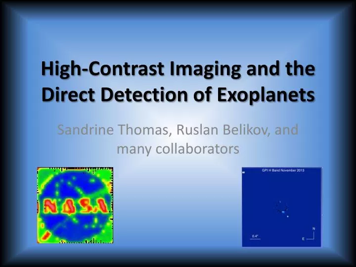
High-Contrast Imaging and the Direct Detection of Exoplanets Sandrine Thomas, RuslanBelikov, and many collaborators
Is there another Earth out there? Is there life on this over Earth? 2
Requirements for habitability not habitable (too small to keep oxygen and water) not habitable (too large, hydrogen gas does not escape) habitable • Planet size: ~ 0.5 – 2 Earth size • Temperature: 0-100 C • Biomarkers: water and oxygen Credit: Petigura/UC Berkeley, Howard/UH-Manoa, Marcy/UC Berkeley H2O (Water) O2 (Oxygen) (Schematic representation only)
VENUS X 0.60 CO2 CO2 EARTH-CIRRUS O2 H2O H2O O2 O3 H2O H2O MARS Iron oxides H2O ice EARTH-OCEAN Spectroscopy: detecting biomarkers Detecting atmospheric oxygen and water likely indicates life (because very few non-biological processes can sustain an oxygen atmosphere) Ref: R. Hanel, GSFC
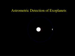
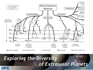
861 confirmed planets (677 planetary systems) 2740 planet candidates (from Kepler mission) (Wobble method #2: Astrometry) Wobble method #1: Radial Velocity Direct detection
Direct ImagingMain Engineering Requirements • Contrast • ~1010 for Earth-like planets • ~107 for young hot planets and disks • Inner Working Angle • The smaller the better! • Typically 1-3 l/D required on missions
Beyond Kepler: Direct imaging missions 2010 2020 2030 Kepler Exo-C/S or AFTA (~1.4m / 2.4m, $1B / $2B+) New Worlds Telescope ($4-8m, $4B+) Small sats (0.25-0.7m, ~$5 – 200M) Earth-size Habitable zone Spectroscopy • Two stars: aCen Earth-size Habitable zone No spectroscopy (biomarkers) Not nearby systems Another Earth? Earth-size Habitable zone Spectroscopy ~6-20 stars Earth-size Habitable zone Spectroscopy ~100s of Earths Simulation of an exo-Earth around aCen with a $1B mission (1.5m telescope) All these missions also do ground-breaking science on non-habitable planets
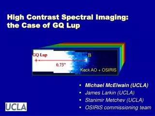
Ground based Instruments:Exoplanet direct imaging instruments GPI SPHERE Macintosh et al, 14 Beuzit et al, 14 P1640 SCExAO Hinkley et al, 08 Guyon et al, 10
High Contrast Imaging Like searching for a firefly next to a lighthouse in San Franciscofrom Boston => Very faint and small in comparison • UpperScorpius • Lafreniere et al 2008 • Beta Pictoris b • Lagrange et al 2010 • HR 8799 • Marois et al 2008 • Fomalhaut b • Kalas et al 2008
5 nm RMS non-common path WFE Limitations • Diffraction from the parent star • Depends on telescope diameter and wavelength: FWHM=lambda/d • Passives and active aberrations in the system • Constant: static aberrations of the system • 1Hz: drifts due to temperature, flexure, mechanical instability. • 1KHz: from the ground: atmosphere • Amplitude errors and Talbot effect that turns amplitude errors into phase errors 1 nm RMS non-common path WFE
Solutions • Diffraction: Coronagraphs • Aberrations: Active and adaptive optics • Wavefront sensor : Shack-Hartmann, curvature sensors • Deformable mirror • Control software Diagram of a direct imaging instrument feedback DM system Coronagraph Science camera from telescope WFS feedback Starlight rejected by coronagraph
Principle of Pupil Apodization-type coronagraphs Image plane starlight Telescope pupil Resulting image
Apodizer manufacture:halftone technique using black chrome microdots The apodizer transmission is obtained by randomly distributing 2μm square dots over the glass. by JenOptiks.
The ApodizedLyot coronagraph Aime et Al. 2001 Pupil plane Focal plane Lyot stop Image
Challenge #2: optical aberrations Image plane starlight Telescope pupil Resulting image
Feedback Adaptive Optics System for Turbulence Correction Distorted wavefront Corrected wavefront Imager DM WFS
Feedback Image sharpening for slow changing aberrations Distorted wavefront Corrected wavefront Imager DM WFS
Speckle Nulling • We need to know how the DM phase maps to the image location and intensity • To calibrate location drive the DM at the highest spatial frequency • To calibrate the intensity measure some of the spatial frequency and interpolate the rest
Lab Performance after Speckle Nulling Before static wavefront correction Example: Gemini Planet Imager, Macintosh B. Savransky, Thomas et al., 2012 After static wavefront correction
Image Sharpening: Ex: Electric Field Conjugation (Give’on et al. 2008, Thomas et al. 2010) • Calculate the electric field (Ef) in the focal plane • Find the DM shape such that its effect in the plane of interest negates the electric field present in this plane • Possible to correct both phase and amplitude Improves the contrast by a factor 3, reaching 4.10^8. G A + Ef = 0 Reconstruction matrix Electric field in the focal plane Actuator commands
The Ames Coronagraph Experiment (ACE) Laboratory • Cooling system • WavefrontControl: SN, EFC, LOWFS MEMS from Boston Micromachine Corporation On stepper and piezo stage
People and organizations partnering with ACE UofA Olivier Guyon Glenn Schneider Julien Lozi L3 Tinsley Jay Daniel AsfawBekele Lee Dettmann Bridget Peters Titus Roff Clay Sylvester NASA ARC Ruslan Belikov Thomas Greene Eugene Pluzhnik Sandrine Thomas Fred Witteborn Dana Lynch Paul Davis Eduardo Bendek Kevin Newman Princeton Jeremy Kasdin Bob Vanderbei David Spergel Alexis Carlotti STScI Laurent Pueyo JPL Brian Kern Andy Kuhnert John Trauger Wes Traub John Krist Marie Levine Stuart Shaklan K. Balasubramanian Lockheed Martin DomenickTenerelli Rick Kendrick Alan Duncan Wes Irwin Troy Hix
Contrast Achieved in air • Median contrast of 4.06x10⁻⁷ between 1.2 and 2 l/d • Simultaneously with 8.51x10⁻⁸ between 2 and 4 l/d • Mask Inner Working Angle (IWA)=1.12 λ/d • Average over an hour • Speckle nulling, round mask
Stability • Contrast remains under 10-6 in the inner region and under 10-7 in the outer region for over an hour, (represented as 1500 images). • Same performance was obtained in three independent tests. • Reapplying a MEMS map 1-day after the correction without changing the calibration keeps the results within 10%. => MEMS stable and reproducible correction
Vacuum tests Monochromatic result • We achieved the same contrast as in air, but on a bigger zone: 1.2-12 λ/D instead of 1.2-4 λ/D • We are close to the milestone in polychromatic (1.8e-7 at 5%, 3.2e-7 at 10% between 2 and 12 λ/D) • Limited now by a manufacturing default of the focal plane mask (OD3 instead of OD5) • A new mask will be manufacture for the last vacuum test, and help us achieve the milestone. Focal plane mask Polychromatic result with bandwidth of 5, 10, 20 and 40 %.
Status/Next steps • Milestone #1 demonstration requirement met (exceeded) in air • 1.8e-7, 1.2-2.0 l/D simultaneously with 6.5e-8, 2.0-4.0 l/D • First vacuum tests started in January and are ongoing • Milestone #2 (10% broadband light) to be pursued this year • EXCEDE aggressive IWA technology development can be beneficially carried over to future larger scale coronagraphic missions with focus on exoplanets • Most of the credit goes to: • J. Lozi: LOWFS, DAQ, system calibration • S. Thomas: Optical design, EFC wavefront control • E. Pluzhnik: Optical assembly and alignment, SN • E. Bendek: CAD design and layout • T. Hix and the rest of the LM team: • Vacuum hardware preparation and chamber operations
Adaptation to halo beam issues • Will need: • Contrast needed? 1e-7? • How far from the core do you need to observe? • Which wavelength? • Dynamic range of the detector • Potential issues: • Static and dynamic aberrations (Stability?) • The source is resolved. • The source size varies with time (how much?) • Noise • Mie scattering? • Figure 1. Lower-dynamic-range transverse beam profile measured in Jefferson Lab’s free-electron laser injector. The blue halo intensity is about 300 (arbitrary units) less than that of the green core. Image courtesy of Pavel Evtushenko Christine Herman, 2001
Need contrast of about 1e-4/1e-5? Christine Herman, 2001
Conclusion • Similar issues are seen by your groups and coronagraphy for astronomy. • Need a translation between astronomy and particle physics
GPI Observations of HR 4796A N 0.5” E Individual 60 s images One linear polarization shown. Waveplate rotates 0, 22.5, 45...& the parallactic angle changes Combined 12 minutes Total intensity Combined 12 minutes Linear polarized intensity Slide by Marshall Perrin