Download
1 / 19
190 likes | 337 Views
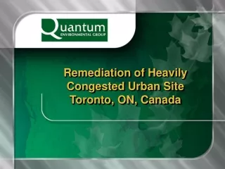
Remediation of Heavily Congested Urban Site Toronto, ON, Canada . Site Location. Located in Toronto, ON – Canada’s largest city Situated in a densely populated, high traffic, mixed use (predominantly residential and commercial) neighbourhood. Site Location.

E N D
Remediation of Heavily Congested Urban SiteToronto, ON, Canada
Site Location Located in Toronto, ON – Canada’s largest city Situated in a densely populated, high traffic, mixed use (predominantly residential and commercial) neighbourhood
Site Location Former Gasoline Dispensing Station contaminated with hydrocarbons at depths of up to 14 meters below grade. A second gasoline dispensing station was located across the street causing contamination under the public roadways. Small site (approximately 1,000 m2) bounded on two sides (North and West) by major urban roads, a 12 storey condominium (East) and low rise retail (South). Major utilities in the road right-of-ways including gas, hydro, water, fibre optic telecommunication, storm and sanitary sewers.Many of the services were between 50 and 100 years old and were directly adjacent to the property boundaries Two stories of underground parking adjacent to the Eastern property line.
Underground Utilities Gas Storm Sewer Sanitary Sewer Water Mains Telephone and Fibre Optic conduits Electrical conduits Central Steam Distribution network
Geotechnical Conditions Highly disturbed soils to a depths of 6 m below grade (due to previous remedial excavation) overlying silt/clay till to 7mbg overlying saturated, unconsolidated sands to full depth. Water table at 8 meters below grade Sands becoming “flowing” or “boiling” at depths in excess of 8 meters below grade
Remedial Action Plan (RAP) Excavate contaminated soil to depth of up to 14.0 m below grade on three property linesinto “flowing” sand formation. Excavation methodology must allow flexibility due to unknown final depth of hydrocarbon contamination; Design and construct shoring to protect off-site public property and neighbouring parking structure with no anchors or tiebacks permitted off of the property; Design and install low-permeability barrier walls (<10E-8 m/s ) on west, east and north property boundaries between 6 and 14 m (max) below gradeinto the water table to ensure no re-contamination of the site from off-site sources (public roadways). Elevated vapour levels and hot-work required on-site
The Solution Installation of H-pile to 11mbg and lagging (inc. rakers) to 7mbg to shore excavation wall on N and E P/L Slurry slots excavations backfilled with low strength concrete from 7 to a maximum of 14 mbg on N and E P/Ls to remove impacted soil and provide hydraulic barrier Installation of caisson wall on W P/L to 11m below grade to support adjacent parade and provide hydraulic barrier Slot excavation of impacts at depth along caisson wall, backfilled with low strength concrete Wet excavation of entire central portion of site
H-Pile and Lagging 600 mm caissons open drilled to 11m, filled with H-pile and low strength concrete (4MPa) Whaler installed at grade and excavation between H-Piles completed with timber lagging Once at 4 mbg, rakers welded and set in 30 MPa concrete footings excavated at 6 mbg Bulk excavation completed to 6 mbg in north and east portion of site.
Confidential Site, Toronto, ON - Bentonite Slurry, Concrete, Caisson Wall
Bentonite Slurry/Concrete Wall Slots excavated up to 14mbg using 5% bentonite slurry to shore excavation wall Slot backfilled with low strength concrete to provide impermeable barrier Alternating slot technique used with over excavation into adjacent slot to ensure continuous impermeable wall Bentonite mixed using shear pump to meet 45 second Marsh Cone viscosity test
Bentonite Slurry/Concrete Wall Advantages • Allows for variable depth profiles • Allows for installation in unconsolidated material • Can be engineered for various design permeabilities (10E-6 to 10E-12 m/s) • Concrete additives (bentonite) can lower permeability • Wall thickness can be designed to meet required flow characteristics • Mix design can provide concrete designs for temporary or permanent structural excavation or building support.
Bentonite Slurry/Concrete Wall Critical Installation/Field Issues • Quality of bentonite will affect stability of slurry • Proper field mixing and QA/QC of bentonite slurry is critical • Entrained sediment will reduce viscosity of slurry in slot (ongoing testing required) • When using slot techniques, over-excavation of low strength concrete is critical to ensure continuous barrier • Slot depth measurement must be accurate to ensure design depth of barrier is correct
Caisson Wall Barrier Installation From 3mbg bench, 13, 600 mm dia. open boreholes were drilled on a specified spacing ~11mbg and filled an H-Pile and LS concrete to 3 mbg; H-Piles were used in select caissons to construct a shoring support wall Subsequently, 3 ‘filler’ boreholes were advanced between each of the 13 previously drilled, reinforced and filled boreholes Filler’ boreholes were drilled with a minimum 0.1m overlap into the adjacent caisson and filled with LS concrete; ’filler’ borehole 2 was drilled first, followed by ‘filler’ boreholes 1 and 3 • A whaler was installed at 4 mbg to further stabilize the cantilevered wall • Bulk excavation was continued to ~8mbg, with slots excavated and backfilled to 11mbg with LS concrete.
Caisson Wall Barrier Installation Advantages Solid structure, cantilevered excavation wall support system • can be advanced right at property line • no off-site encroachment or agreements necessary • no rakers required (simplifies backfilling) Shoring excavation support and impermeable barrier installed simultaneously Low strength concrete can be easily excavated for site servicing (vs. pulling H-piles and lagging)
Caisson Wall Barrier Installation Critical Installation/Field Issues • QA/QC of caisson locations is critical to ensure correct overlaps • Auger/caisson advancement must be closely monitored for plumb, particularly for deep barrier walls as off-plumb alignment will cause gaps in the barrier wall • Soils should be free of large obstructions as augers will drift off-plumb • Soils should be sufficiently consolidated so that augers do not drift off-plumb when advancing ‘filler’ boreholes