Download
1 / 39
390 likes | 499 Views
NML High Energy Beam Absorbers and Dump. 29-August-2011 Beams-doc-3928. NML Beam Absorbers Outline. System Overview Absorber Design and Analysis Assembly Dump Shielding Design Installation Summary and Status. System Overview.

E N D
NML High Energy Beam Absorbers and Dump 29-August-2011 Beams-doc-3928
NML Beam AbsorbersOutline • System Overview • Absorber • Design and Analysis • Assembly • Dump Shielding • Design • Installation • Summary and Status
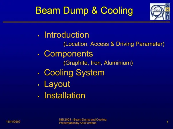
System Overview • Dump concept, configuration and radiation design by Church and Rakhno • Dump houses 2 water-cooled absorbers • Each absorber contains two independent cooling loops • Each circuit accepts 30gpm flow rate • Single RAW skid can feed multiple cooling circuits simultaneously
Key Requirements • Beam Parameters • 1.5 GeV, 3.33 nC/bunch, 3MHz, 1ms pulse @ 5Hz • 3.12 E14 electrons/s • 75kW beam • Absorber shall be capable of accepting beam continuously (i.e. steady state operation) • Absorber shall have a design lifetime of 20 years, assuming a 70% operation factor (i.e. 123,000 hours) • Absorber cores shall not require servicing • Absorbers shall provide a redundant cooling circuit
Absorber Core Configuration 0.5m 1.85m 0.5m
NML Beam AbsorbersOutline • System Overview • Absorber • Design and Analysis • Assembly • Dump Shielding • Design • Installation • Summary and Status
Absorber Core Configuration Water cooling in integral channels Al Graphite Al Cu/Steel
Graphite/Aluminum Contact Architecture Primary Circuit Outlet Redundant Circuit Outlet graphite Fastener-preloaded contact: top and bottom No contact on sides Primary Circuit Inlet Redundant Circuit Inlet
Thermal Analysis Approach • Step 1: Process MARS results in Excel • Tabulate X, Y, Z and heat generation for each MARS element • Step 2: Generate mechanical FEA models in NX/Ansys • Two meshes are used: • System Model: assess global effects • Axial Section Model: assess localized heating in graphite • Tabulate FEA mesh nodal and element XYZ locations • Step 3: Interpolate MARS results onto FEA mesh in Matlab • Use MARS radiation damage estimates to assign material properties • Map heat generation results from MARS mesh onto arbitrary FEA mesh • Calculate heat generation at each FEA element • Generate Ansys text input using BFE/HGEN • Step 4: Run Ansys to recover temperatures
MARS Model: (I. Rakhno) C Al H2O Cu y y x z
MARS ResultsHeat Generation (W/m3): linear color scale C Al H2O Cu/Steel y z Max: 1.32E8 W/m3 @ Z=.35m
MARS ResultsHeat Generation (W/m3): log color scale 10n C Al H2O Cu/Steel y z Max: 1.32E8 W/m3 @ Z=.35m NML Beam Absorber Analysis
Steady State Analyses • The steady state thermal analyses neglect the pulsed nature of the energy deposition, and assume constant and continuous beam power • We use two sets of graphite properties: • Beginning of Life (BOL) – graphite properties not degraded by radiation damage (but still fully temperature dependant) • End of Life (EOL) – graphite damage categorized in bins, corresponding degraded material properties mapped onto the FEA mesh • We further use two sets of beam conditions • Centered beam – the original, intuitive design concept • Off-center beam – implemented to distribute graphite damage and prevent catastrophic failure • In general, the worst cases are off-center beams at EOL
System Model Steady StateCentered Beam @BOLMaximum temperature in graphite and system Z Max Temperature in Graphite 643°C @ Z=.482m
Radiation Effects: Graphite Thermal Conductivity Reduction Example data
MARS Results (I. Rakhno) DPA/year for a stationary beam: log color scale 10n C Al H2O Cu y z Max: 0.14 DPA/beam-year in graphite 0.20 DPA/beam-year in Al
Cumulative Damage20years, 70% uptime, full beam power Distributed beam Maximum damage = 0.22 dpa Z Z Stationary beam: Max damage = 2.8 dpa Maroon area exceeds 0.25 dpa damage threshold
Mapping of k Reductionat EOL on Graphite Core Migrating Beam Material 205 Damage>.02 dpa Material 204 .01< Damage <.02 dpa Z Z Material 203 .001< Damage <.01 dpa Material 202 .0001< Damage <.001 dpa
System Model Steady StateCentered Beam @EOLMaximum temperature in graphite and system Z Max Temperature in Graphite = 1703°C (compare to 643°C @BOL)
Absorber Mechanical Design • Based on the results and recommendations of the thermal analysis, a detailed mechanical design was completed
NML Beam AbsorbersOutline • System Overview • Absorber • Design and Analysis • Assembly • Dump Shielding • Design • Installation • Summary and Status
Component-Level Assembly and Test • Much effort was put into meticulously assembling, sealing, and testing the individual cooling plates
Assembly and Test • Cooling plates were then assembled and interconnected via 1.5”-Schedule 40 stainless interconnect lines
Assembly and Test • Completed plumbing circuits were then hydrostatically and pneumatically tested to ensure a leak-tight system
Assembly and Test • In the final step of absorber assembly, a helium-filled enclosure will be constructed around the absorber cores.
NML Beam AbsorbersOutline • System Overview • Absorber • Design and Analysis • Assembly • Dump Shielding • Design • Installation • Summary and Status
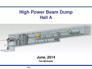
Dump Shielding Design • The dump shielding was specified by the Church/Rakhno radiation design • The shielding around the absorbers is 24’ X 20’ X 24’ • ~570 tons concrete • ~620 tons steel • Designed following established best-practices • seams, gaps carefully managed
NML Beam AbsorbersOutline • System Overview • Absorber • Design and Analysis • Assembly • Dump Shielding • Design • Installation • Summary and Status
Dump Shielding Installation • The vast majority of the steel was obtained from the railhead • Steel was measured, labeled, and cut to a common length
Dump Shielding Installation • The first phase of dump installation has been completed • Second phase awaiting absorber completion
NML Beam AbsorbersOutline • System Overview • Absorber • Design and Analysis • Assembly • Dump Shielding • Design • Installation • Summary and Status
Status • The assembly of the individual absorbers is nearly complete • After the helium enclosures are welded and tested, we will install the absorbers in the dump • Task completion this fall