Download
1 / 21
210 likes | 376 Views
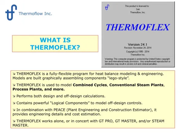
What is THERMOFLEX. Thermoflow, Inc. WHAT IS THERMOFLEX?. THERMOFLEX is a fully-flexible program for heat balance modeling & engineering. Models are built graphically assembling components “lego-style”.

E N D
What is THERMOFLEX Thermoflow, Inc. WHAT IS THERMOFLEX? • THERMOFLEX is a fully-flexible program for heat balance modeling & engineering. Models are built graphically assembling components “lego-style”. • THERMOFLEX is used to model Combined Cycles, Conventional Steam Plants, Process Plants, and more. • Performs both design and off-design calculations. • Contains powerful “Logical Components” to model off-design controls • In combination with PEACE (Plant Engineering and Construction Estimator), itprovides engineering details and cost estimation. • THERMOFLEX works alone, or in concert with GT PRO, GT MASTER, and/or STEAM MASTER.
Overview THERMOFLEX begins in “Stage1: Draw System”. You have a blank sheet on which you draw your model by connecting icons from the icon bar at the bottom. Alternatively, you can start by loading an existing file, or importing an existing GT PRO file. THERMOFLEX has a clearly organized structure. At any time you work in one of four stages shown here. You can easily move from stage to stage, and back again as needed to refine and redefine your model.
Basic Functionality A context sensitive help system gives you access to the entire THERMOFLEX manual Drawing screen – drag components from the component bar at the bottom to construct your model. Green tab holdsPEACE components which use physical equipment models. These models generate spec sheets and cost estimates on output. Pointing at an iconproduces an enlargedimage with its connectionpoints and its full name. Each tab summons a different component bar with its own set of components. In total approximately 130 components are available. Individual component icons
Draw System The model has two screens: One for steam turbine and one for boiler. You may place components on up to 10 separate screens for ease of navigation or better clarity. Here, we are in the middle of creating a coal fired conventional steam cycle using mainly PEACE components. Each node on the components has beenconnected to another component eitherdirectly or through a connector (black line).
Check Drawing Once the plant drawing is completed, press this ‘Check Drawing’ button to transition from ‘Stage 1: Draw System’ to ‘Stage 2: Edit Inputs’. LP turbine HPT IPT LP FWH train HP FWH train Water Cooled Condensers connected to Wet Cooling Tower. Condensing reheat steam turbine (screen 1 of 2)
Design – Edit Inputs Now we are in Stage 2: Edit Inputs. The screen background is solid gray to distinguish it from the previous stage, ‘Stage 1: Draw System’. All numerical inputs for each component and overall plant are initialized with defaults. The model may be computed at any time from this stage. Each component has its own input screen like this one shown for the rotary air heater. You can review defaults, and edit inputs to suit your needs. Double-click anyicon to summon its input screen.
Design – Edit ST Assembly Input The steam turbine type and configuration was defined. In this case a four casing reheat configuration is chosen. The assembly manager then automatically establishes defaults for leakages that you can accept or edit below. THERMOFLEX has “Assembly” models that provide additional features for a collection of components. While a steam turbine section itself does not have a cost output, a steam turbine assembly consisting of one or more sections does. Once the components are “in” the assembly, other detailed input screens are available to specify leakages, last stage bucket data, and other details.
Design – Check Inputs and Activate Calculation After editing inputs the model the user can performCheck Inputs and activate the Calculation. Computation progress isdisplayed in a separate window. By the way, THERMOFLEX has a large library containing sample files describing different types of plants and models.This example is one of the sample files.
Design – Computation Complete & Warnings Computation has completed andmessages can be displayed. Advisory and Warning messages
Design – General Output General output screen One way of displayingthe outputs is throughstream tags.
Design – Component Output Heat Balance Each componenthas a similaroutput graphicwhich can bedisplayed in allprogram modes. PEACE componentsalso have atabulatedoutput form. Final heat balance data are displayed on this graphic. TQ-diagram
Design – Component Output Hardware One of four tabs with tables describing details of theevaporator and one drawing showing the tube bundle. Second HP superheater hardware designedby the program in Designmode. These tabulated outputs are available for PEACE components only.
Design – ST Assembly Output General cycle performance data can be displayed. Steam turbine thermodynamic data and hardware are described in sub-tabs applying data from each component in the assembly. HPT IPT LPTs Generator Steam turbine main dimensions.
PEACE Output – Example of cost Size & Cost of the steam turbine. Steam Turbine main dimensions from Specification tab. Steam Turbine elevation view. Steam Turbine cost fromSpecification tab.
Off-Design – Edit Boiler Load In Off-design the user canperform simulations withthe design. Plant load can be adjusted by setting the appropriate boiler load. In Off-design the user can adjust hardware for all PEACE components to match an existing plant or vendor data.
Off-Design – Edit Steam turbine control To perform batches of runs toexplore plant performanceMultiple Runs are available. ST inlet pressure control.
Off-Design - Output In general Off-design outputs are similar to Design outputs. The stream table can be displayed both in Design and Off-design mode. The stream table canbe exported to Excelto work on additionalgraphic displays orcalculations.
Program Options Common unit systems fromaround the world are supportedby THERMOFLEX. Also the steam property formulation may be selected. Available formulations: Thermoflow Proprietary (STQUIK) IFC-67 (previous ASME standard from 1967) IAPWS-IF97 (current ASME standard from 1997)
Multiple Runs – Edit Input Thermoflow Macro enables the user to performseries of calculations in an easy and fast way. Part load calculations with constant ambient conditions. Inputs to vary in themacro may be selectedfrom an extensive listof inputs availablefrom THERMOFLEX. Full load calculations with varyingsite ambient temperature.
Multiple Runs - Output Plant Summary and the two subsequent tabs display fixed lists of output data. Any of the general tabs allows theuser to define which data (outputsas well as inputs) to display in thatspecific table. All tables can be exported to Exceldirectly or saved as a .CSV file forlater load into Excel. For each case THERMOFLEXoutput can be displayed. Plots can be created.As an example Net efficiency vs. Boiler load.
More Information Please contact Thermoflow for further information and a Demonstration CD. THERMOFLOW, INC. 29 Hudson Road, Sudbury Massachusetts 01776 USA Tel: +1-978-579-7999 Fax: +1-978-579-5995 E-mail: info@thermoflow.com