Download
1 / 36
360 likes | 523 Views
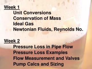
Week 1 Unit Conversions Mass and Volume Flow Ideal Gas Newtonian Fluids, Reynolds No . Week 2 Pressure Loss in Pipe Flow Pressure Loss Examples Flow Measurement and Valves Pump Calcs and Sizing.

E N D
Week 1 Unit Conversions Mass and Volume Flow Ideal Gas Newtonian Fluids, Reynolds No. Week 2 Pressure Loss in Pipe Flow Pressure Loss Examples Flow Measurement and Valves Pump Calcsand Sizing
1000 gallons of wortis transferred from a kettle through a 100 m long, 4 cm diameter pipe with a roughness of 0.01 mm. The wort flows at an average velocity of 1.2 m/s and assume that its physical properties are the same as those of water (μ = 0.001 Pa.s). • Determine the time required to transfer all of the wort to the boil kettle, in min. • Determine the Reynolds Number. • Determine the pressure drop in the pipe.
Friction Losses in Pipes found on Moody Chart handout Determine the pressure drop of water, moving through a 5 cm diameter, 100 m long pipe at an average velocity of 5 m/s. The density of the water is 1000 kg/m3 and the viscosity is 0.001 Pa.s. The pipe roughness is 0.05 mm.
Valves – Globe Valve Single Seat - Good general purpose - Good seal at shutoff Double Seat - Higher flow rates - Poor shutoff (2 ports) Three-way - Mixing or diverting - As disc adjusted, flow to one channel increased, flow to other decreased
Valves – Butterfly Valve Low Cost “Food Grade” Poor flow control Can be automated
Valves – Mix-proof Double Seat Two separate sealing elements keeping the two fluids separated. Keeps fluids from mixing Immediate indication of failure Automated, Sanitary apps Easier and Cheaper than using manyseparate valves
Valves – Gate Valve Little flow control, simple, reliable
Valves – Ball Valve Very little pressure loss, little flow control
Valves – Brewery Applications Product Routing – Tight shutoff, material compatibility, CIP critical Butterfly and mixproof Service Routing – Tight shutoff and high temperature and pressure Ball, Gate, Globe Flow Control – Precise control of passage area Globe (and needle), Butterfly Pressure Relief – Control a downstream pressure
Flow Measurement Principle: • Bernoulli Equation • Notice how this works for static fluids.
Flow Measurement – Orifice Meter • Cd accounts for frictional loss, 0.65 • Simple design, fabrication • High turbulence, significant uncertainty P1 P2
Flow Meas. – Venturi Meter • Less frictional losses, Cd 0.95 • Low pressure drop, but expensive • Higher accuracy than orifice plate P1 P2
Flow Meas. – Variable Area/Rotameter Inexpensive, good flow rate indicator Good for liquids or gases No remote sensing, limited accuracy
Flow Measurement - Pitot Tube • Direct velocity measurement (not flow rate) • Measure P with gauge, transducer, or manometer P1 P2 1 2 v
Flow Measurement – Weir Open channel flow, height determines flow Inexpensive, good flow rate indicator Good for estimating flow to sewer Can measure height using ultrasonic meter
Flow Measurement – Thermal Mass Measure gas or liquid temperature upstream and downstream of heater Must know specific heat of fluid Know power going to heater Calculate flow rate
Flow Measurement – Magnetic Faradays Law Magnetic field applied to the tube Voltage created proportional to velocity Requires a conducting fluid (non-DI water)
Pumps z = static head hf = head loss due to friction Suction Pump Delivery
Pumps Calculate the theoretical pump power required to raise 1000 m3 per day of water from 1 bar to 16 bar pressure. If the pump efficiency is 55%, calculate the shaft power required. Denisityof Water = 1000 kg/m3 1 bar = 100 kPa
Pumps A pump, located at the outlet of tank A, must transfer 10 m3 of fluid into tank B in 20 minutes or less. The water level in tank A is 3 m above the pump, the pipe roughness is 0.05 mm, and the pump efficiency is 55%. The fluid density is 975 kg/m3 and the viscosity is 0.00045 Pa.s. Both tanks are at atmospheric pressure. Determine the total head and pump input and output power. 4 m Tank B 15 m Pipe Diameter, 50 mm Fittings = 5 m Tank A 8 m
Pumps Need Available NPSH > Pump Required NPSH Avoid Cavitation z = static head hf = head loss due to friction
Pumps A pump, located at the outlet of tank A, must transfer 10 m3 of fluid into tank B in 20 minutes or less. The water level in tank A is 3 m above the pump, the pipe roughness is 0.05 mm, and the pump efficiency is 55%. The fluid density is 975 kg/m3 and the viscosity is 0.00045 Pa.s. The vapor pressure is 50 kPa and the tank is at atmospheric pressure. Determine the available NPSH. 4 m Tank B 15 m Pipe Diameter, 50 mm Fittings = 5 m Tank A 8 m
Pump Sizing • Volume Flow Rate (m3/hr or gpm) • Total Head, h (m or ft) • 2a. P (bar, kPa, psi) • Power Output (kW or hp) • NPSH Required
Pumps Centrifugal Impeller spinning inside fluid Kinetic energy to pressure Flow controlled by Pdelivery Positive Displacement Flow independent of Pdelivery Many configurations
Centrifugal Pumps Delivery Impeller Volute Casting Suction
Centrifugal Pumps Flow accelerated (forced by impeller) Then, flow decelerated (pressure increases) Low pressure at center “draws” in fluid Pump should be full of liquid at all times Flow controlled by delivery side valve May operate against closed valve Seal between rotating shaft and casing
Centrifugal Pumps Advantages Simple construction, many materials No valves, can be cleaned in place Relatively inexpensive, low maintenance Steady delivery, versatile Operates at high speed (electric motor) Wide operating range (flow and head) Disadvantages Multiple stages needed for high pressures Poor efficiency for high viscosity fluids Must prime pump
Centrifugal Pumps H-V Chart Increasing Impeller Diameter Head (or P) A B C Volume Flow Rate
Centrifugal Pumps H-Q Chart Increasing Efficiency Head (or P) Required NPSH A B C Volume Flow Rate
Centrifugal Pumps H-Q Chart Head (or P) A B C Volume Flow Rate
Centrifugal Pumps H-Q Chart Required Flow Capacity Head (or P) Actual Flow Capacity Required Power Volume Flow Rate
Pump Sizing Example Requirements 100 gpm 45 feet of head Choose the proper impeller Determine the power input to the pump
Pressure Drop Example Water flows through a 10 cm diameter, 300 m long pipe at a velocity of 2 m/s. The density is 1000 kg/m3, the viscosity is 0.001 Pa.s and the pipe roughness is 0.01 mm. Determine: a. Volume flow rate, in m3/s b. Mass flow rate in kg/s c. Pressure loss through the pipe, in Pa d. Head loss through the pipe meters