Download

1 / 21
210 likes | 477 Views
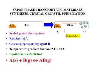
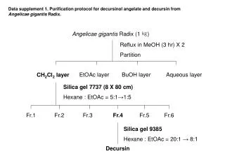
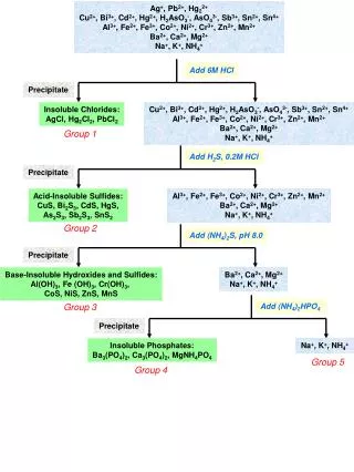
3D Modeling and Simulation of Hg 2 Cl 2 Crystal Growth by Physical Vapor Transport. Joseph Dobmeier Advisor: Patrick Tebbe Minnesota State University November 2011. Introduction. Hg 2 Cl 2 crystals are useful for their acousto-optic properties.

E N D
3D Modeling and Simulation of Hg2Cl2 Crystal Growth by Physical Vapor Transport Joseph Dobmeier Advisor: Patrick Tebbe Minnesota State University November 2011
Introduction • Hg2Cl2 crystals are useful for their acousto-optic properties • Used to construct acousto-optic modulators and tunable filters in the low UV and long wave infrared regions 8-10μm[1] Image from Kima et. al., 2008 • Applications include: laser Q-switches, fiber-optic signal modulators, spectrometer frequency control
Introduction • Two technologically mature and commercially available materials for this region are Terillium Oxide (TeO2) and Thalium Arsenide-Selenide (TAS) Image from http://www.olympusfluoview.com/theory/aotfintro.html • TeO2 is fragile and prone to damage • TAS is extremely toxic and requires specialized handling
Introduction Images from Kima et. al., 2008
Outline • Modeling • Simulation • Results • Future Research Directions
Modeling • Four conservation equations[2-4]:
Modeling • Geometry: • Vertically oriented 5x5cm cylinder with the source at the bottom • Boundary conditions: • Walls: no slip, adiabatic, and impermeable • Source and sink: constant temperature, tangential velocity of zero, normal velocity calculated using Fick’s law and Dalton’s law of partial pressures[6]
Outline • Modeling • Simulation • Results • Future Research Directions
Simulation • Performed by a commercially available code FIDAP, a product of Fluent Inc. • Capabilities extended to physical vapor transport process through the use of a subroutine • Subroutine determines the boundary nodal velocities by a finite difference calculation of the mass fraction derivatives • Each nodal velocity was then scaled to ensure source and crystal mass flux average values satisfied the continuity equation[2] • Initial conditions for velocity were zero, a linear profile was selected for the concentration profile
Simulation • Mesh density: • Parametric studies were performed in 2D on the mesh density • Three sizes were compared: • 31x31 • 61x61 • 121x121 • Flowfield development was found to be identical, but some small-scale recirculation cells were not captured • A frequency analysis was undertaken comparing the oscillatory regions which agreed across densities
Simulation • Table of parameters used in study (Ts = 330°C):
Outline • Modeling • Simulation • Results • Future Research Directions
Results • Case 1:
Results • Case 2:
Results • Case 5:
Results Case 5 (0.33, 0, 0.5) Case 1 (0, 0, 0.5) Case 2 (0, 0, 0.5) Case 3 (0.49, 0, 0.4)
Outline • Modeling • Simulation • Results • Future Research Directions
Future Research • Complete bifurcation graph showing flowfield regime transition • Perform phase-space analysis of transient and oscillatory regions • Simulate more cases for current geometry • Modify geometry for different furnace layouts • Reduce total run time through parallel implementation of simulation with newer commercial software code
References [1] Joo-SooKima, Sudhir B. Trivedia, JolantaSoosa, NeelamGuptab, WitoldPalosza. Growth of Hg2Cl2 and Hg2Br2 single crystals by physical vapor transport. Journal of Crystal Growth 310 (2008) 2457–2463. [2] P. A. Tebbe, S.K. Loyalka, W. M. B. Duval. Finite element modeling of asymmetric and transient flowfields during physical vapor transport. Finite Elements in Analysis and Design 40 (2004) 1499-1519. [3] W. M. B. Duval, Convection in the physical vapor transport process-I: thermal, J. Chem. Vapor Deposition 2 (1994) 188-217. [4] W. M. B. Duval, Convection in the physical vapor transport process-II: thermosolutal, J. Chem. Vapor Deposition 2 (1994) 282-311. [5] D. W.Greenwell, B. L. Markham and F. Rosenberger. Numerical modeling of diffusive physical vapor transport in cylindrical ampoules, Journal of Crystal Growth, 51 (1981) 413-425. [6] R. B. Bird, W.E Stewart and E. M. Lightfoot. Transport Phenomena 2nd Ed., John Wiley & Sons Inc., (2002) 268, 353-356. [7] F.C. Moon. Chaotic and Fractal Dynamics. John Wiley & Sons Inc., (1992) 53-55.