Download
1 / 11
110 likes | 319 Views
Metering Philosophy under ABT regime. NTPC Station. Aux. Aux. Aux. M2. M1. B. A. C. D. E. C1. C2. ISGS -I. H. S2. G. S1. F F'. J J'. K K'. L. M. SEB-A. ISTS. S. T. U. W. V. N. O. P. SEB-B. R. ISTS. Q. SEB-B. SEB-A. ISGS-II injection Main = (M1+M2)

E N D
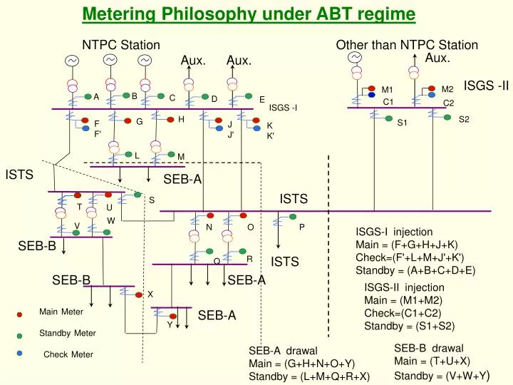
Metering Philosophy under ABT regime NTPC Station Aux. Aux. Aux. M2 M1 B A C D E C1 C2 ISGS -I H S2 G S1 F F' J J' K K' L M SEB-A ISTS S T U W V N O P SEB-B R ISTS Q SEB-B SEB-A ISGS-II injection Main = (M1+M2) Check=(C1+C2) Standby = (S1+S2) X SEB-A MainMeter Y StandbyMeter CheckMeter Other than NTPC Station ISGS -II ISTS ISGS-I injection Main = (F+G+H+J+K) Check=(F'+L+M+J'+K') Standby = (A+B+C+D+E) SEB-B drawal Main = (T+U+X) Standby = (V+W+Y) SEB-A drawal Main = (G+H+N+O+Y) Standby = (L+M+Q+R+X)
Points for Energy Accounting Injection by NTPC Generating Stations : Main &check meters on Outgoing feeders Standby meters on HV side of GT/TT Injection by other Generating Stations : Main &check meters on HV side of GT/TT Standby meters on Outgoing feeders Drawl by SEBs Main -HV side of ICTs at GS and CTU S/S, Receiving end of Lines directly connected to ISGS Respective ends of Lines connected to other SEBs Standby – LV/ Tertiary side of ICTs Other end of lines connected to other SEBs
Special Energy Meter Features STATIC TYPE COMPOSITE METER HIGHEST ACCURACY IN POWER INDUSTRY 3 PHASE-4 WIRE CONNECTIONS / MEASUREMENT DIRECT MEASUREMENT AS PER CT/PT SECONDARY QUANTITIES - 110V PH TO PH/63.51 V PH-N - 1 AMP OR 5 AMP VA BURDEN NOT >10 ON ANY OF THE PHASES WORKS ON REAL TIME CLOCK NO CALIBRATION REQUIRED TIME ADJUSTMENT FACILITY HIGH SECURITY OF DATA STORAGE
Raw data WEEK FROM 0000 HRS OF 06-01-01 TO 0837 HRS OF 15-01-01 NP-0185-A 91858.5 99968.5 39195.5 06-01-01 00 51 +21.57 48 +21.68 50 +21.71 49 +21.33 …. 04 19 +20.61 23 +20.80 19 +21.05 00 +21.35 … 08 00 +24.95 00 +24.95 00 +25.09 00 +24.38 … 12 71 +24.38 52 +23.98 30 +23.81 13 +24.03 … 16 00 +23.37 00 +23.52 00 +22.87 00 +21.66 … 20 00 +25.75 00 +25.32 00 +25.40 00 +25.37 … NP-0185-A 94117.2 99968.5 40313.5 07-01-01 00 59 +20.94 54 +21.01 59 +20.79 58 +21.05 … 04 33 +20.05 38 +20.17 37 +20.49 28 +20.90 … 08 00 +22.99 06 +23.10 00 +22.81 00 +22.94 … 12 85 +20.93 51 +20.65 21 +20.79 00 +19.89 … 16 07 +20.14 01 +20.53 00 +20.72 00 +20.66 … 20 05 +23.62 08 +23.23 16 +23.25 27 +23.40 … NP-0185-A 96172.2 99968.5 41236.9 08-01-01
Special Energy Meter Various Checks CHECKS for DATA VALIDATION : • NOMINAL VOLTAGE CHECK • FREQUENCY • TIME CORRECTION • WATTHOUR CHECK • PREVIOUS WEEK DATA • ALGEBRAIC SUM
Special Energy Meter Data Computing • RAW DATA IN WHr • MWhr = RAW DATA x CT RATIO x PT RATIO • PAIR CHECK DONE FOR MAIN/ CHECK/ STANDBY/ FICTMETERS ( ex. : for both sides of ICTs, Lines, GT side & Line side at ISGS.
Reactive Energy Accounting Reactive Energy is measuredwhen system voltage is > 103% of Nominal Voltage< 97% of Nominal Voltage
Loss computations 15 min block-wise % loss = (Sum of all Injections from ISGS + net IR imports) - (Sum of Drawals by all beneficiaries from Central Grid) X 100 (Sum of all Injections from ISGS + net IR imports)
Use of Notional Loss in scheduling • % Average loss (15 min. blockwise) aggregated over the last week will be used in Scheduling Process for the next week. (for arriving at the ex-periphery Drawal Schedules of Beneficiaries) • 0.5% REDUCTION MEANS MORE THAN 100 CR ANNUAL SAVINGS Loss Table %loss Graph
TYPICAL %AVERAGE LOSS FIGURES FOR CENTRAL GRID IN SR OTHER REGIONS %Average losses In other Regions : NR 3.5 to 4.5 ER 3.0 to 3.5 WR 5.0 to 6.0 BACK