Download
1 / 81
810 likes | 929 Views
NAT NPX138N VHF-FM Radio Part I Briefing on General Use and Settings. DEWG CAP 5/23/00. Ver. 1.0. How to Navigate this course. How to Navigate this course. This presentation has animation sequences to help demonstrate the way some things work.

E N D
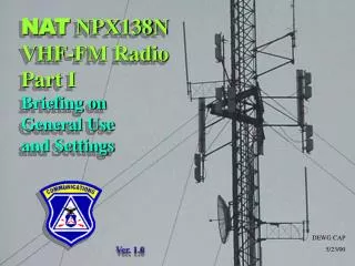
NATNPX138N VHF-FM RadioPart IBriefing on General Use and Settings DEWG CAP 5/23/00 Ver. 1.0
How to Navigate this course How to Navigate this course This presentation has animation sequences to help demonstrate the way some things work This presentation has animation sequences to help demonstrate the way some things work In order to allow you to get the most out of these aids, you’ll be afforded the ability to move forward at your own pace. You’ll know it’s your turn to go forward in the presentation when you see this button Page Up or NEXT Press any key once you see this. The space-bar works great as an “any key”. If you want to replay animation, use the Page Up key on your PC, and press any key to restart that part Page Up or NEXT Go ahead and try this on your own:
This is the NPX-138 radio from Northern Airborne Technology, Ltd of Canada which has been designated as CAP’s aircraft VHF-FM radio of choice. • FAA accepted for aircraft use • 100 channels within the 138-174 mHz VHF spectrum • “Guard” (priority) channel monitor capability • Programmable from laptop computer in the field [Page Up orNEXT
Introduction “NEXT” “HELP” …if you want to search the built-in tutorials, you can press the white button marked “help” at this time. Otherwise, you may go to the Channel Display by lightly toggling the BRIGHTNESS switch, also labeled “NEXT”, either direction. Page Up orNEXT
Introduction The position of the EDIT switch governs the way in which the other switches operate. This is a pull-type lockout toggle switch DON’T move this until you cover Part II, Advanced Training on field program options and scanning The EDIT switch centered, the function of the other chief toggle switches are as labeled above them: Display, Channel, and Brightness. Page Up orNEXT Page Up orNEXT
Introduction • Some of the more obvious controls are right here: • Main Volume - Adjusts receiver volume • Display Type - Changes display mode • Some of the more obvious controls are right here: • Main Volume - Adjusts receiver volume • Display Type - Changes display mode • Some of the more obvious controls are right here: • Main Volume - Adjusts receiver volume • Display Type - Changes display mode • Channel Select - Choose the channel you want • Brightness - Adjust the screen brightness • Channel Select - Choose the channel you want • Brightness - Adjust the screen brightness • Channel Select - Choose the channel you want • Brightness - Adjust the screen brightness Page Up orNEXT Page Up orNEXT
Introduction • Scan Select - allows scanning or no scanning • Guard Channel Volume and Guard Select - allow use of second receiver circuit on a Guard frequency • Scan Select - allows scanning or no scanning • Guard Channel Volume and Guard Select - allow use of second receiver circuit on a Guard frequency Page Up orNEXT
Introduction Operating the Radio Let’s cover these functions in greater detail There are two possible screen readout types to observe, and you may use which ever you prefer: This “Alpha-Numeric” readout………. Page Up orNEXT
Operating the Radio ……....Or this “Frequency” readout. Page Up orNEXT
Operating the Radio • Display Switch to the left shows the ID Display • Switch to the center is the Receive Display. This is the actual receive frequency for this “channel” The DISPLAY switch lets you choose the display mode. Page Up orNEXT Page Up orNEXT
Operating the Radio • You recall from ROA training that a “channel” is comprised of 1) a radio frequency, and 2) a subaudible note, or tone, which rides underneath the voice audio and opens up other radios’ receivers • The tone for this channel is 100 cycles, or Hertz • See the number to the right of the RF frequency. This is the subaudiable tone, or CTCSS tone which is programmed for that channel • Switch to the right is the Transmit Display. The TX and RX frequency will most often be the same in airborne communications Exceptions will arise. Page Up orNEXT Page Up orNEXT
Operating the Radio • This screen shows everything one really needs to know while in the air: • The Channel, as known on our other VHF-FM radios In the interest of safety and confusion avoidance, it’s recommended that the radio is left in…… …this ID Display condition …this ID Display condition This is your preferred, typical view screen. …this ID Display condition • Thenormal use or tasking for that channel Page Up orNEXT Page Up orNEXT
Getting Started Operating the Radio • Power display - HI = 10 Watts, LO = 1 Watt • HI Power would be the normal setting • CTCSS Tone On or Off • “ON” would be the normal setting Page Up orNEXT
Operating the Radio • Notice that we didn’t specify the means for changing the variables such as tone, power, etc • Once this radio is installed and programmed, it should just power up and operate “as is” Page Up orNEXT
Operating the Radio • Part II, the Advanced User segment of this training series will cover the specifics of changing the options for tone, power, and other matters • These functions need not be altered in any way, as long as the display reads as just specified Page Up orNEXT
Operating the Radio Here’s an overview of the other chief functions: • On/Off and Volume - Traditional function and purpose • On/Off and Volume - Traditional function and purpose • Squelch - Push in to hear the weakest of signals • Squelch - Push in to hear the weakest of signals • Channel - Pick the channel of operation desired • Channel - Pick the channel of operation desired Page Up orNEXT
Operating the Radio • If one considers just this much, the NPX-138N works just like any other VHF-FM radio • Turn on, set channel, adjust volume as required • Turn on, set channel, adjust volume as required • Turn on, set channel, adjust volume as required • Turn on, set channel, adjust volume as required • Set display mode and screen brightness • Set display mode and screen brightness • Set display mode and screen brightness • Set aircraft comm panel as necessary Page Up orNEXT
Operating the Radio • If one considers just this much of the radios operation, it works just like any other VHF-FM radio • Leave the scan select on NORMAL, or centered • Leave the scan select on NORMAL, or centered
Operating the Radio • If one considers just this much of the radios operation, it works just like any other VHF-FM radio • Leave the scan select on NORMAL, or centered • Press in the Squelch button to hear very weak signals • Press in the Squelch button to hear very weak signals
Operating the Radio • If one considers just this much of the radios operation, it works just like any other VHF-FM radio • Leave the scan select on NORMAL, or centered • Press in the Squelch button to hear very weak signals • Change channels as required during mission • Change channels as required Page Up orNEXT
Operating the Radio “So, just what is this ‘Guard Channel’ feature, anyway?” • Set the Guard VolumeControlcounterclockwiseto it’s lowest setting for now • Set the Guard VolumeControl counterclockwiseto it’s lowest setting for now • Switch the Guard Channel Select to channel 1 or 2 depending upon the needs of your local Command • Switch the Guard Channel Select to channel 1 or 2 depending upon the needs of your local Command Page Up orNEXT Page Up orNEXT
Imagine your radio is actually -- 2 radios in one! • You could work one channel while listening to another Here’s how to use the Guard feature: • You could go “off frequency” with a ground team, and still catch a call on your primary channel from Mission Base (or from another air crew or ground team) • National F-1 and F-4 are default programmed as GD1& GD2 • Use the Guard Select switch to choose which guard channel to monitor - the repeater or the air-ground frequency • Use the Guard Select switch to choose which guard channel to monitor - the repeater or the air-ground frequency • Use the Guard Select switch to choose which guard channel to monitor - the repeater or the air-ground frequency • You could be doing work with another agency on their channel, and still receive a CAP mission alert • Leave the SCAN switch in NORMal mode for now • You could answer these calls without switching the dial • Set the Guard Volume to a desired level Page Up orNEXT Page Up orNEXT Page Up orNEXT Page Up orNEXT Page Up orNEXT
Choose your other operating channel with the CHANnel switch, in the common fashion for channel selection • If you hear a call and the lamp immediately to the right of the regular on-off-volume knob lights up, then that was on the regular channel as indicated on your display • Answer that call in the regular fashion, you don’t have to change or move anything on the radio to do so Page Up orNEXT Page Up orNEXT
If you hear a call and the lamp just to the right of the Guard Channel (GD) knob lights up - • If you hear a call and the lamp just to the right of the Guard Channel (GD) knob lights up - then you would: • Adjust the GD Volume if necessary for good audio • Change the SCAN/NORM switch to the bottom setting, which is labeled “GD TX” - Guard Transmit • Change the SCAN/NORM switch to the bottom setting, which is labeled “GD TX” - Guard Transmit • Change the SCAN/NORM switch to the bottom setting, which is labeled “GD TX” - Guard Transmit • All transmissions from you will now go out over the Guard Channel you selected with the switch GD1/GD2 Page Up orNEXT Page Up orNEXT Page Up orNEXT
It should be pointed out that Guard Channel/Regular Channel co-monitoring is no different than the way we use the aircraft aviation band comm radios… You can hear traffic on either one, but they both have their own volume and TX controls • Once all Guard Channel traffic is cleared, you would - • Revert back to normal operation by switching the SCAN/NORM switch back up to where it was before • Adjust Main and Guard volumes, as necessary • Simply set the NPX-138N’s two volume knobs as needed & answer either “radio” by means of the NORM - GD TX switch • Continue normal operations • Guard Volume has a preset minimum volume level • Guard Volume has apreset minimumvolume level Page Up orNEXT Page Up orNEXT Page Up orNEXT
Operating the Radio Final Practical Review … And that’s it !! So, Let’s review just once more on the important stuff: • We know we need to see a channel display of one kind or the other, so we can use the radio. - You see this “HELP” screen, so you would do what in order to get past this screen and on to business? Page Up orNEXT Toggle the switch labeled “BRIGHTNESS”/”NEXT” NEXT for Answer
Final Practical Review - You can display the Channel by Frequency or by it’s “name” or common usage. Choose this how? Page Up orNEXT Toggle the switch labeled “DISP”, for “Display” NEXT for Answer
Final Practical Review • We’re asked to go off to another channel to assist an outside agency on a mission or work a ground team • How do we keep an ear out for Mission Base as well? Use the Guard switch, choose GD 2 for CAP-4, & you’ll hear calls on either frequency NEXT for Answer Page Up orNEXT
Final Practical Review • ….and so you’re on your agency assist and you hear a call from another CAP airplane on GD 2, which you know is CAP’s Channel 4 Page Up orNEXT • What’s the fastest, easiest way to answer them? This switch all the way down, and speak to them NEXT for Answer
Final Practical Review Conclusion This is for timing • There’s absolutely no substitute for hands-on field experience • Try these basic steps while you’re on the ground, so that they become second-nature when you’re in the air That’s it! • Now that you’ve seen this, the radio owners manual should be reviewed -- while you’re sitting in front of the radio if possible
This is the end of the Introductory Level Briefing on the basic useof the NPX138N from NAT, Ltd Continue with the Advanced User Briefing to learn to use Scanning, Priority, and Direct Frequency or Channel Editing
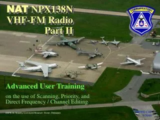
NATNPX138N VHF-FM RadioPart II Advanced User Trainingon the use of Scanning, Priority, and Direct Frequency / Channel Editing DEWG CAP 9/30/00 DAFB Air Mobility Command Museum Dover, Delaware
This is the Advanced Training for use of the NPX-138 from Northern Airborne Technology • Specific assumptions are made that the student understands the purpose of certain VHF-FM specific matters [such as CTCSS tones], and is comfortable with prior instruction on general use as covered under Part I of this user training series • It is assumed for the purposes of this advanced training that the operator/student has at least some experience with frequency agile radios • Examples of such are aviation band comm radios or certain VHF-FM applications [Page Up] orNEXT [Page Up] orNEXT Remember, this means you may press any key to continue
Proceed further if you desire information on Channel Scanning, Priority Scanning, and in-the-field frequency entry. Do so only if you feel entirely confident with the preceding material under Part I, the Basic NPX-138N User Training. [[Page Up] orNEXT
Review One makes display selections by means of 4 toggle switches. Many radios will arrive with the default screen shown here. Your radio can be re-programmed to come on and go directly to the channel position of your choice. For now, let’s assume this is what you see…. Most references to adjustments will be with respect to one or more of these switches. [Page Up] orNEXT [Page Up] orNEXT
Review “NEXT” • IF your radio does power up with this screen, simply move the “NEXT” {Brightness} toggle to the left or right • We now see the normal operating screen [Page Up] orNEXT [Page Up] orNEXT
Review X X X “And how, exactly, do I do that?”, you ask. • The EDIT switch is normally centered so that important settings don’t get messed up • You can, however, make corrections to TONE, POWER, SIMPLEX/DUPLEX, SCAN & PRIORITY choices by this means • You can, however, make corrections to TONE, POWER, SIMPLEX/DUPLEX, SCAN & PRIORITY choices by this means • You can, however, make corrections to TONE, POWER, SIMPLEX/DUPLEX, SCAN & PRIORITY choices by this means • You can, however, make corrections to TONE, POWER, SIMPLEX/DUPLEX, SCAN & PRIORITY choices by this means • You can, however, make corrections to TONE, POWER, SIMPLEX/DUPLEX, SCAN & PRIORITY choices by this means • You can, however, make corrections to TONE, POWER, SIMPLEX/DUPLEX, SCAN & PRIORITY choices by this means [Page Up] orNEXT [Page Up] orNEXT
Setting Options • The important mode selections are STEPPED through, one at a time, by moving the EDIT switch to the right -- to the STep position • The important mode selections are STEPPED through, one at a time, by moving the EDIT switch to the right -- to the STep position [Page Up] orNEXT
Setting Options • The important selections are STEPPED through, one at a time, by moving the EDIT switch to the right -- to the STep position • The EDIT switch in this position changes the mode of these other two switches to NEXT and SELECT, as labeled below them • The EDIT switch in this position changes the mode of these other two switches to NEXT and SELECT, as labeled below them • The EDIT switch in this position changes the mode of these other two switches to NEXT and SELECT, as labeled below them • The EDIT switch in this position changes the mode of these other two switches to NEXT and SELECT, as labeled below them [Page Up] orNEXT
Setting Options • Toggling the switch labeled NEXT takes you through the different modes or settings which can be adjusted, such as Power, Tones, Scan, etc • These settings are “global” - They affect all channels, not just the one displayed at the time [Page Up] orNEXT
Setting Options • The SELECT toggle makes the desired change, such as (selection) On, (selection) Off, or setting High or Low, etc • The key is knowing what it is you want or need [Page Up] orNEXT
Setting Options “SELECT” “NEXT” • So we know now that we can change various parameters by running thru them one at a time with the NEXT switch • So we know now that we can change various parameters by running thru them one at a time with the NEXT switch • And we know we can execute the change by toggling the SELECT switch. • And we know we can execute the change by toggling the SELECT switch. [Page Up] orNEXT [Page Up] orNEXT
Setting Options • The Transmit mode should be left in DUPLEX, so that repeater channels will work. Duplex channels use one frequency for transmit and another for receive • The first variable which comes up is the Simplex/Duplex selection • The next variable in this sequence is the POWER OUTPUT with a choice of HI, which is 10 Watts of power (max allowed in CAP air service), or LO, which is 1 Watt • One usually thinks of Simplex operation as direct, radio-to-radio contact, while Duplex is most often associated with repeater use • Channels meant to be “Simplex” , such as 1 thru 4, have been programmed with TX and RX the same so they will act as simplex channels just fine [Page Up] orNEXT [Page Up] orNEXT [Page Up] orNEXT [Page Up] orNEXT
Setting Options • The TONES selection is the next variable • You recall from ROA training that a “channel” is comprised of 1) a radio frequency, and, 2) a sub-audible note, or tone, which rides underneath the voice audio and opens up other radios’ receivers • The choices for the TONES setting are: ON, OFF, or TX ONLY. Leave “ON” for most general use • IF you need to hear a channel without your receiver tone filter on, “TX ONLY” does this. Don’t ever set to “TONES=OFF”. This cuts TX tones as well & you’ll forget, leaving it unusable for future air crews. [Page Up] orNEXT [Page Up] orNEXT
Setting Options • The next changeable option is the TONE DISPlay. • The TONE DISPlay mode determines how that tone is labeled, for programming or reference purposes • In order to explain it’s significance, take a look at the main screen again, in this DISPlay mode • Choices are the audio frequency itself, such as 100.0, or the EIA# such as “12”, or other nomenclatures used by the Motorola or Wulfsberg companies • Assume you’re now in the RX Display mode [Page Up] orNEXT [Page Up] orNEXT [Page Up] orNEXT
Setting Options • We refer to tone types in both simplex and repeater service by their frequency - 156.7 Hz, 203.5 Hz, etc • This will become important if you should need to install other users’ channels in the field [Page Up] orNEXT [Page Up] orNEXT [Page Up] orNEXT [Page Up] orNEXT
Setting Options • The next selectable options are the SCAN bank designator and the PRIORITY selector • These two functions and their set-up are related, so we’ll cover them together in just a moment • So, “TONE DISPlay” is simply a choice of ways to refer to the CTCSS tones you may need to enter in the field • Let’s go back to the STep SELECTion we just left, showing the TONE DISP option and continue from there…... [Page Up] orNEXT [Page Up] orNEXT
Setting Options • Another selection along in the Step process lets you choose the channel you see when you POWER-UP the radio [Page Up] orNEXT
Setting Options Once all of the STepped variables have been set, return the EDIT switch to the center position. Consider leaving all settings as show above: Verify that you left : • We didn’t go through all selections possible within each variable option category • Most people won’t need to change any of these aforementioned selections, but it’s good to know how to do so in the field or on a mission POWER = HI DISPlay Switch = ID Channel = Air to Ground or as directed by your local command SCAN Switch = Normal Guard1/Guard2 = G1 or as directed by local command EDIT Switch = <Centered> TONES = ON [Page Up] orNEXT [Page Up] orNEXT [Page Up] orNEXT [Page Up] orNEXT [Page Up] orNEXT [Page Up] orNEXT [Page Up] orNEXT [Page Up] orNEXT [Page Up] orNEXT
Advanced User Training • OK, let’s cover Channel Scan and Priority • Scanning is the process of allowing the radio to listen to many channels in a repeating sequence • The receiver stops on a channel if it’s in use, so you can hear if there’s traffic of interest to you [Page Up] orNEXT