Download
1 / 48
1.26k likes | 2.91k Views
ITU/WMO Seminar on Use of Radio Spectrum for Meteorology: Weather, Water and Climate Monitoring and Prediction”. Wind Profiler Radars. 6.2. Naoki Tsukamoto Japan Meteorological Agency 17 Sep. 2009. Wind Profiler Radars. Contents Introduction User requirement

E N D
ITU/WMO Seminar on Use of Radio Spectrum for Meteorology: Weather, Water and Climate Monitoring and Prediction” Wind Profiler Radars 6.2 Naoki Tsukamoto Japan Meteorological Agency 17 Sep. 2009
Wind Profiler Radars • Contents • Introduction • User requirement • Operational and frequency aspects • Spectrum requirement • Sharing aspects of wind profilers • Japanese wind profiler network 6.2 Wind Profiler Radars
INTRODUCTION • What is a Wind Profiler Radar? • Advantages of WPRs • RASS 6.2 Wind Profiler Radars
What is a wind profiler radar? • Wind Profiler Radars (WPRs) are used to obtain the vertical profiles of the wind over an unattended and sometimes remote area by detecting the tiny fraction of emitted power backscattered from turbulence in the clear atmosphere. Air flow Wind vector Reflected radio wave Emitted radio wave Principle of measuring wind by WPRs The frequency of reflected radio wave is changed by Doppler effect. 6.2 Wind Profiler Radars
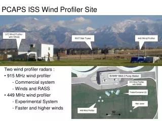
example of wind profiler installation 449MHz WPR RASS This picture is from the Handbook(2008) 6.2 Wind Profiler Radars
example of wind profiler installation Snow covered area type (f = 1357.5MHz) General structure in Japan(f = 1357.5MHz) Redome: for antenna protection from snow 6.2 Wind Profiler Radars
Advantages of WPRs • One of the major advantages of wind profilers to other wind measurement systems is their ability to continuously monitor the wind field. • they can also be used to • detect precipitation, • measure major disturbances in the vertical velocity, • measure the intensity turbulence, • measure atmospheric stability. 6.2 Wind Profiler Radars
Example of WPR’s data As an example mobile profiling system operating at 924 MHz produced the plot of wind velocity vs. altitude. The orientation of each flag represents wind direction as a function of altitude (vertical axis)and time (horizontal axis), while its colour represents wind speed. This is from Handbook(2008) 6.2 Wind Profiler Radars
Advantages of WPRs • WPRs can also provide detailed information on atmospheric virtual temperature through the addition of a Radio Acoustic Sounding System (RASS) 6.2 Wind Profiler Radars
Acoustic Wave The speed of sound Electromagnetic Wave (The speed of light) RASS WPR RASS RASS RASS RASS • RASS utilizes an acoustic source that is matched in frequency so that the wavelength of the acoustic wave is matched to half the wavelength of the radar transmitted electromagnetic wave. 6.2 Wind Profiler Radars
Acoustic Wave The speed of sound Electromagnetic Wave (The speed of light) RASS WPR RASS RASS RASS RASS • RASS measures the speed of the acoustic wave which is dependent upon temperature. • In this way RASS provides a remote measurement of the atmospheric virtual temperature. 6.2 Wind Profiler Radars
User requirement A good way to examine the impact of user requirements upon wind profiler operating parameters and design is to consider the following equation rewritten from [Gossard and Strauch, 1983]: 6.2 Wind Profiler Radars
User requirement • High temporal resolution • High vertical resolution • Obtaining wind data at high altitudes • Reliable all-weather operation 6.2 Wind Profiler Radars
User requirement • High temporal resolution • Large aperture • High peak power and high pulse repetition frequency (PRF) • Long wave length • Operation over a range of heights close to the radar • High PRF does not cause range ambiguity • Atmospheric backscattering are relatively large 6.2 Wind Profiler Radars
User requirement • High vertical resolution • large aperture • high peak power, high PRF, and pulse compression to increase the average power • long wavelength • operation over a range of heights close to the radar where high PRF does not cause range ambiguity problems and where atmospheric backscattering and inverse-height-squared are relatively large 6.2 Wind Profiler Radars
User requirement • Obtaining wind data at high altitudes • large aperture; • high peak power and pulse compression to increase the average power; • long wavelength; • large averaging times. 6.2 Wind Profiler Radars
User requirement • Reliable all-weather operation even if low-scatter conditions • frequency band; • high average power and antenna aperture; • higher receiver sensitivity; and • low level of interference and system noise. 6.2 Wind Profiler Radars
Monthly average of highest altitude for wind data both Non-Precipitation condition Precipitation condition Winter in Japan low humidity Low Tropopause altitude highest altitude for wind data [m] Apr Mar 6.2 Wind Profiler Radars
Operational and frequency aspects • Three types of WPRs • 50MHz band WPRs • Middle and Upper atmosphere radar • 400MHz band WPRs • 1000MHz or more band WPRs • Boundary layer radar 6.2 Wind Profiler Radars
Comparison 50, 400, 1300MHz 30km Stratosphere 15km Troposphere 5km 6.2 Wind Profiler Radars
Operational and frequency aspects • MU radar( 50MHz band) is very large, powerful and short pulse • About 10 000m2, • 250kW or more peak, 12.5kW or more average • Pulse width: 1 microsecond 6.2 Wind Profiler Radars
Operational and frequency aspects • 400-500MHz Wind profiler have been designed to : • Measure wind profiles from about 0.5 - 16km • Vertical resolutions: • 250m( low altitude) • 1000m( high altitude) • Antenna gain is about 32dBi, • Mean power of: • about 500W( low altitude) • About 2000W( high altitude) • Necessary bandwidth of less than 2MHz 6.2 Wind Profiler Radars
Operational and frequency aspects • 915MHz and 1270-1375MHz Wind profiler have been designed to : boundary layer profiler, • Measure wind profiles up to about 5km • Vertical resolutions are about 100m • Antenna gain is below 30dBi, • Mean powers of about 50W • Necessary bandwidths of 8MHz or more 6.2 Wind Profiler Radars
spectrum requirements • Geographical separation and terrain shielding are effective protection against interference to and from other profilers. • Hence, an affordable network of wind profilers, say separated by at least 50 km over level terrain – less over more rugged or treed terrain – could operate on the same frequency. 6.2 Wind Profiler Radars
spectrum requirements • It is generally agreed that 2 to 3 MHz of bandwidth are required near 400 MHz and 8 to 10 MHz near 1 000 MHz or 1 300 MHz 6.2 Wind Profiler Radars
Sharing aspects of wind profilers • The bands for profiler use allocated by WRC-97 were carefully selected to minimize the likelihood of interference to and from other users of these bands. • 46-68 MHz in accordance with No. 5.162A • 440-450 MHz • 470-494 MHz in accordance with No. 5.291A • 904-928 MHz in Region 2 only • 1 270-1 295 MHz • 1 300-1 375 MHz 6.2 Wind Profiler Radars
An example of a WPR network • The Japan Meteorological Agency (JMA) is operating a Wind profiler Network and Data Acquisition System (WINDAS) network. • Consist of thirty-one 1.3GHz wind profiler 6.2 Wind Profiler Radars
WINDAS • Purpose of WINDAS • Monitoring and Predicting the severe weather • Initial value of JMA Numerical Weather Prediction models • Combined with another data to comprehensive Upper-air wind analysis 6.2 Wind Profiler Radars
WINDAS Wind Profiler Network and Data Acquisition System
JMA Upper-air Observation Network Wakkanai 31 Wind Profilers Wind Profiler Control Center 16 Radiosonde stations Rumoi Sapporo Nemuro Muroran Obihiro Akita Miyako Sakata Takada Hamada Fukui Takamatu Kumagaya Tottori Mito Yonago Wajima Tateno Oita Control Center (JMA Headquarters) Mihama Izuhara Katuura Fukuoka Kawaguchiko Hirado Shiono- misaki Hachijojima Kumamoto Shizuoka Ichiki Kagoshima Nagoya Kouchi Owase Yakushima Shimizu Nobeoka Naze Chichijima Minamidaitojima Ishigakijima 1000km Minamitorishima Yonagunijima JMA upper-air observation network consisting of rawinsonde stations and wind profilers of WINDAS. Upper-wind observations are made at the interval of about 120km. 6.2 Wind Profiler Radars
Data Flow in WINDAS WINDAS Profiler3 Profiler30 Profiler2 10 minute values of Doppler velocity and signal intensity being sent every 1 hour Profiler1 Profiler31 Data quality control and remote control of profilers being made CONTROL CENTER(JMA Headquarters) Horizontal and vertical components of wind and signal intensity being sent with BUFR code every 1 hour C O S M E T S (JMA Central Computer) ADESS N A P S Every 6 hours 10 minute data being sent every 1 hour Every 1 hour Forecast made with Mesoscale Model Hourly analyzed atmospheric GPV Wind profiler data 6.2 Wind Profiler Radars
Appearance General structure (Kagoshima: Department observedIchiki) Snow-covered area (Hokkaido: Department observed Obihiro) 6.2 Wind Profiler Radars
Major equipment and signal flow Module Unit Antenna System CONTROL CENTER Transmitter and Receiver System Data Processer 6.2 Wind Profiler Radars
Block Diagram of the JMA Wind Profiler Network ( WINDAS) CONTROL CENTER OBSERVATION SITE Type A 中央監視局 Antenna System 観測局 Transmitter and Receiver System Module Unit LAN Server 1 Server 2 L3SW HUB L2SW L3SW Operating Display Data Processer Printer HUB L2SW Leased line 国内基盤通信網 Type B Weather station Outdoor Operating & Watching Quality Control L2SW Data Processer L3SW Observation hut Router Router HUB ISDN Operating Display Data Processer 6.2 Wind Profiler Radars
Characteristics of the JMA Wind Profiler 6.2 Wind Profiler Radars
Data Quality Control W P R Data Processor W P R Receiver W P R Signal Processor Network Center F F T / Wavelet White Noise Rejection Ground Clutter Rejection line Spectra Rejection Multi-Peak Processing Receiving Power Check Horizontal Buddy Check Spectrum Width Check Surface Wind Check Velocity Unfolding Quadratic Surface Check Time-Height Check Vertical Shear Check 10 Min. U,V,W Spectrum Data Development of QC Algorithm 1 Min. Doppler Velocity 10 Min. U,V,W JMA Central Computer 6.2 Wind Profiler Radars
Example of data 6.2 Wind Profiler Radars
Surface weather map Yakushima Typhoon was 980 hPa, moving to ENE 13kt near Yakushima WPR site. 6.2 Wind Profiler Radars
Satellite image 6.2 Wind Profiler Radars
台風13号通過(屋久島) 2008/09/1812:00-18:00 Yakushima Vertical velocity Vertical velocity 鉛直速度 S/N比 鉛直シアー 東西成分 南北成分 スペクトル幅 受信強度 6.2 Wind Profiler Radars ヘリシティ
台風13号通過(屋久島) 2008/09/1812:00-18:00 Yakushima SNR 鉛直速度 S/N比 鉛直シアー 東西成分 南北成分 スペクトル幅 受信強度 6.2 Wind Profiler Radars ヘリシティ
台風13号通過(屋久島) 2008/09/1812:00-18:00 Yakushima Vertical Shear of horizontal wind speed Vertical Shear 鉛直速度 S/N比 鉛直シアー 東西成分 南北成分 スペクトル幅 受信強度 6.2 Wind Profiler Radars ヘリシティ
台風13号通過(屋久島) 2008/09/1812:00-18:00 Yakushima East-West component East-west component 鉛直速度 S/N比 鉛直シアー 東西成分 南北成分 スペクトル幅 受信強度 6.2 Wind Profiler Radars ヘリシティ
台風13号通過(屋久島) 2008/09/1812:00-18:00 Yakushima North-South component North-south component 鉛直速度 S/N比 鉛直シアー 東西成分 南北成分 スペクトル幅 受信強度 6.2 Wind Profiler Radars ヘリシティ
台風13号通過(屋久島) 2008/09/1812:00-18:00 Yakushima Spectral width Spectral width 鉛直速度 S/N比 鉛直シアー 東西成分 南北成分 スペクトル幅 受信強度 6.2 Wind Profiler Radars ヘリシティ
台風13号通過(屋久島) 2008/09/1812:00-18:00 Yakushima Received Intensity Received intensity 鉛直速度 S/N比 鉛直シアー 東西成分 南北成分 スペクトル幅 受信強度 6.2 Wind Profiler Radars ヘリシティ
SUMMARY • WPRs are used to obtain the upper-air wind and other useful data continuously. • WPRs contains various type, and they use 50MHz band , 400-500MHz band or 900-1400MHz band. • In Japan, data of WPRs are used in various scenes, and very useful. 6.2 Wind Profiler Radars