Download
1 / 23
260 likes | 974 Views
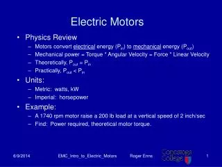
SECTION 4 ELECTRIC MOTORS UNIT 19 MOTOR CONTROLS. UNIT OBJECTIVES. Describe the differences between relays, contactors and starters Explain why the locked rotor amperage (LRA) affects the choice of a motor starter List the component parts of contactors and starters

E N D
SECTION 4 ELECTRIC MOTORS UNIT 19 MOTOR CONTROLS
UNIT OBJECTIVES • Describe the differences between relays, contactors and starters • Explain why the locked rotor amperage (LRA) affects the choice of a • motor starter • List the component parts of contactors and starters • Name two types of external motor overload protection • Explain the differences between external overload protection devices • Explain the conditions under which motor safeties can be reset After studying this unit, the reader should be able to
INTRODUCTION TO MOTOR CONTROL DEVICES • Relays, contactors and starters pass power to the motor by closing sets of contacts • Contacts controlled by coils in the control circuit • Starting relays are only in the active circuit for a short period of time • The type of motor control used is determined by the size and application of the motor used
L1 L2 RELAY OR CONTACTOR CONTROL CIRCUIT MOTOR RUN START RELAY START
L1 L2 RELAY OR CONTACTOR CONTROL CIRCUIT MOTOR RUN START RELAY START
MOTOR AMPERAGES • Running load amperage (RLA) • Similar to full load amperage (FLA) • Amperage drawn by the motor while operating • Locked rotor amperage (LRA) • Amperage drawn by motor on startup • Five to seven times greater than RLA or FLA • Both LRA and RLA must be considered when choosing a control device
THE RELAY • Uses a magnetic coil to open or close one or more sets of electric contacts • The most common control voltage for both relays and contactors is 24 volts. • Relays are not repaired. Replace on failure. • Used for light duty applications • Can be used as a pilot-duty relay • The relay contacts must be able to handle the amperage draw of the load being controlled • Pilot relays are designed to switch on and off larger contactors or starters. They are very light duty and are not designed to start motors directly.
NORMALLY OPEN CONTACTS NORMALLY CLOSED CONTACTS COIL
THE CONTACTOR • Larger version of the relay • Has movable and stationary contacts • Often times only one set of contacts opens which opens only one side of the power to condensing units. This provides power for off-cycle heat to the compressor. • Holding coils are rated at different voltages • Can have one or more sets of contacts • Some are equipped with auxiliary contacts, which are usually rated at a lower amperage than the primary contacts. • Contacts and coils can be replaced, the material most used on the contacts is silver. • Use the exact replacement whenever possible
MOVABLE CONTACTS AND ARMATURE STATIONARY CONTACTS COIL CONNECTIONS STATIONARY CONTACTS HOLDING COIL
WHEN THE COIL IS ENERGIZED, THE CONTACTS ARE PULLED CLOSED The most common coil voltage is 24 volts.
L1 T1 L2 T2 L3 T3 STATIONARY CONTACTS MOVABLE CONTACTS SPRINGS COIL STATIONARY ELECTROMAGNET ARMATURE When contactor is energized what resistance would you expect to read between L1 to T1, L2 to T2 and L3 to T3? - Springs maintain pressure on the contacts for current carrying capacity and they help obtain equal contacts against the stationary contacts. If placing one lead of your voltage meter on T1 and the other on L1, what voltage would you expect to read if the coil is energized?
MOTOR STARTERS • Contactor equipped with overload protection, which actually are designed to protect the motor where fuses or circuit breakers protect the entire circuit. • High amp draw will cause the starter to open. • Coils, contacts and heaters can be replaced • Contacts become pitted over time • Pitting increases the resistance across the contacts, if the pitting is bad enough it can cause motor burn out. • The voltage across the contacts will increase • The voltage across a good set of contacts should be about zero volts
CLEAN CONTACT The most common material used for the contacts is silver. DIRTY, PITTED CONTACT Dirty contacts don’t necessarily mean they are pitted, the sure sign of pitted contacts is increased voltage across the contacts. Sanding contacts will only speed up the deterioration of the contact surfaces.
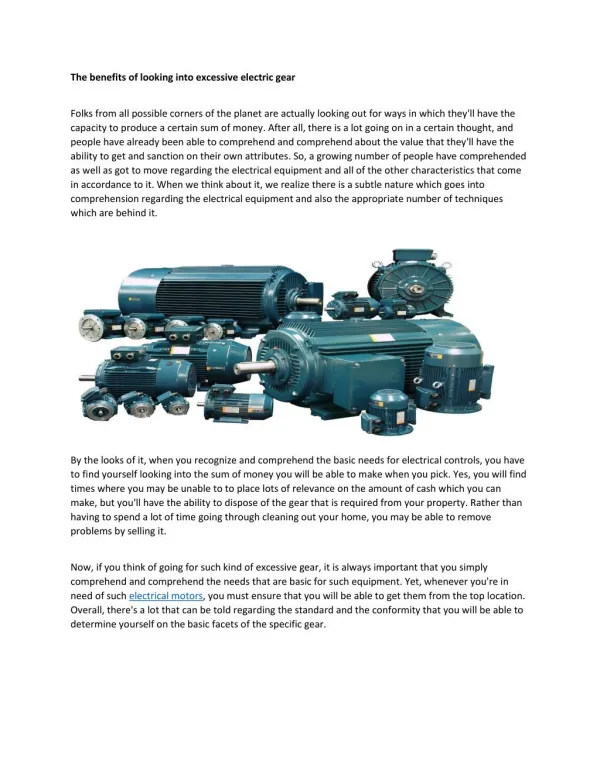
MOTOR PROTECTION • Motors are expensive and must be protected • Fuses and circuit breakers protect the entire circuit, not the individual circuit components • Motors can operate under an overcurrent condition for a short period of time • Most small motors have no overload protection • The larger the motor, the more elaborate the method of motor protection should be • Motor protection can be inherent (internal) or external • Motor service factor is determined by the motor’s reserve capacity
L1 L2 FUSES PROTECT THE ENTIRE CIRCUIT, NOT THE INDIVIDUAL COMPONENTS 25A 3A
INHERENT (INTERNAL) MOTOR PROTECTION • Thermally activated devices in the motor winding. • Internal thermal overloads • Usually embedded in the motor windings • Open on a rise in temperature • Thermally activated bimetal snap discs • Positioned so that contact is made between the bimetal control and the motor • Snap action opens contacts if the motor temperature rises above the desired level
EXTERNAL MOTOR PROTECTION • Devices that pass power to the holding coil of the starter or contactor • Devices open when an overcurrent condition exists • The trip point and type of overload protector are determined by the manufacturer • The overload device takes the service factor of the motor into consideration
NATIONAL ELECTRIC CODE (NEC) STANDARDS • Sets standards for electrical installations • Conductor sizes and ampacities • Cable materials and applications • Electrical devices • Sets standards for motor overload protection • The published code book should be consulted if questions or concerns are encountered on the job
TEMPERATURE-SENSING DEVICES • Bimetal elements • Devices called heaters wired in series with the load • The heater is exposed to the current draw of the load • The bimetal warps and open when it gets too warm • The open bimetal de-energizes the starter holding coil • Solder pot • Uses solder with a low melting point • The solder melts when excessive temperature is sensed • Excessive heat results from the overcurrent condition • Look @ Figure 19-21 on page 366
MAGNETIC OVERLOAD DEVICES • The most accurate means of electrical overload protection • Device is not attached to the starter • Device is not affected by increased ambient temperatures • The contacts within the device will open to de-energize the motor at the desired amperage level
RESTARTING THE MOTOR • Motors should not be restarted immediately • Cause for the overload condition must first be located and repaired • Motor must be given ample time to cool • Many control devices are manually reset, this is to ensure that technicians are aware of a possible problem which caused the starter to trip in the first place. • Some controls reset automatically after a predetermined time delay • Time delay feature prevents short cycling
UNIT SUMMARY • Relays, contactors and starters pass power to motors • Contacts controlled by control circuit holding coils • Relays are used for light duty, contactors for heavier duty applications, starters have built-in overloads • Contacts on contactors and starters can be replaced • Fuses and circuit breakers protect the entire circuit, not the individual circuit components • Motor protect can be inherent or external