Download
1 / 20
200 likes | 285 Views
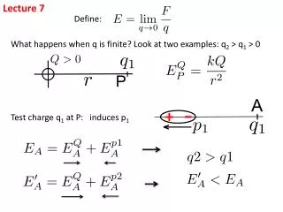
Lecture 7 Curve Turn. Basic Concepts. Keep speed with certain ratio between 2 wheels for mouse to make mouse turn at certain angular velocity However this is not possible in real word When on straight, VLs=VRs When turn VLt > VRt

E N D
Basic Concepts • Keep speed with certain ratio between 2 wheels for mouse to make mouse turn at certain angular velocity • However this is not possible in real word • When on straight, VLs=VRs • When turn VLt>VRt • Motor can’t suddenly change speed from VLs to VLt, and VRs to VRt
Diagram view This is not possible in real world!
Alternative solution Make one wheel accelerate, the other wheel decelerate to reach different speed gradually
How to maintain same turn angle in this way? • All you need to do is just to keep the grey area equals to the sum of red and blue area to maintain the same turning angle
Some facts • The center speed of mouse remains constant when turning since VC = (VL + VR)/2 • VR – VL is still the rotational feedback when turning • You can use the feedback from gyro to replace VR-VL to prevent slippage, however needs to be scale to fit the system with encoder ticks
The view of angular velocity • W(omega) = VR – VL in our system • Diagram in angular velocity form is more straight forward since the center linear velocity of mouse doesn’t change during the turn
Keep the area same • As long you keep the area same between ideal and actual angular velocity, the mouse will turn with same angle you desired • Some extra time is usually needed for actual turn
How to design your profile? • Decide the max angular velocity W(omega) • Decide the angular acceleration (alpha) • Calculate the area for idea turn, make the actual turn area equals to it • Use matlab, excel to make your profile, and keep track of the position of the mouse at each millisecond, keep adjusting the input parameters, until the actual output curve for mouse exits at same location with idea curve • Apply the parameter decided from simulation profile to your mouse
How to make it work on mouse? • Center forward linear velocity, turn angle, angular acceleration, max angular velocity are all know in this case. • Assume T1 = T3 to simplify the case where the slope(angular acceleration rate) are same • Calculate the corresponding angular velocity with T1, slope or max angular velocity at T1 and T3 • The angular velocity is max angular velocity at T2
Sample code • Having this is your controller: • If currentSpeedW < targetSpeedW { currentSpeedW += accW if currentSpeedW > targetSpeedW currentSpeedW = targetSpeedW } else If currentSpeedW> targetSpeedW { currentSpeedW-= accW if currentSpeedW< targetSpeedW currentSpeedW = targetSpeedW }
Sample cont. • The code for your turn function • Void turn(void) { if(is at T1 or T2) targetSpeedW = maxAngularVelocity; else if(is at T3) targetSpeedW = 0; }
Things need to know • The angular velocity has different sign between left turn and right turn • Record the system time in millisecond to keep track of you current time for curve turn. • The angular velocity you generate from provided excel profile generator is in degree/s unit, you need to convert to recognizable unit of mouse
Unit conversion for speed profile • Angular velocity in encoder format equals to: wheelDistance*angularVelocity*Pi*oneCellDistance/cellLength/180/1000 • Where • wheelDistance is distance between centers of the wheels • angularVelocity is the angular velocity in degree/s • OneCellDistance is the encoder counts per cell for one wheel • CellLength is the length of each cell, which is 180mm • /180 is divide 180 degree • /1000 converts from /s to /ms
How to convert for gyro feedback • The intermediate unit between gyro and encoder is distance(meter) • Use pivot turn method to make conversion, where VL = -VR • Record the angle output from gyro when make a 180 degree turn(either directions), as “a” • Get distance value of • 2*Pi*R which is Pi*W in SI unit then convert to encoder counts, as “b”
Unit Conversion (cont.) • You get the ratio between b and a as “Ratio” = a/b (usually a > b) • Now you can apply the ratio to the angular velocity read from gyro and have it easily convert to encoder format: angularFeedback = aSpeed/Ratio angularFeedback also equals VR-VL by definition in controller lecture - Now you can only use gyro as rotational feedback for curve turn