Download
1 / 44
440 likes | 572 Views
HDL-Based Digital Design Part I: Introduction to VHDL (I). Dr. Yingtao Jiang Department Electrical and Computer Engineering University of Nevada Las Vegas Summer 2005. What is VHDL?. VHDL: V HSIC H ardware D escription L anguage VHSIC: V ery H igh S peed I ntegrated C ircuit

E N D
HDL-Based Digital DesignPart I: Introduction to VHDL (I) Dr. Yingtao Jiang Department Electrical and Computer Engineering University of Nevada Las Vegas Summer 2005
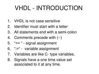
What is VHDL? • VHDL: VHSICHardwareDescriptionLanguage • VHSIC: Very High Speed Integrated Circuit • Developed originally by DARPA • for specifying digital systems • International IEEE standard (IEEE 1076-1993) • Hardware Description, Simulation, Synthesis • Practical benefits: • a mechanism for digital design and reusable design documentation • Model interoperability among vendors • Third party vendor support • Design re-use.
VHDL vs. C/Pascal • C/Pascal: • Procedural programming languages • Typically describe procedures for computing a maths function or manipulation of data (e.g., sorting, matrix computing) • A program is a recipe or a sequence of steps for how to perform a computation or manipulate data. • VHDL: • a language to describe digital systems. • Purposes: simulation and synthesis of digital systems.
Let’s Start Simple • Support different description levels • Structural (specifying interconnections of the gates), • Dataflow (specifying logic equations), and • Behavioral (specifying behavior)
Domains and Levels of Modeling Functional Structural high level of abstraction low level of abstraction “Y-chart” due to Gajski & Kahn Geometric
Domains and Levels of Modeling Functional Structural Algorithm(behavioral) Register-TransferLanguage Boolean Equation Differential Equation “Y-chart” due to Gajski & Kahn Geometric
Domains and Levels of Modeling Functional Structural Processor-MemorySwitch Register-Transfer Gate Transistor Geometric “Y-chart” due to Gajski & Kahn
Domains and Levels of Modeling Functional Structural Polygons Sticks Standard Cells Floor Plan Geometric “Y-chart” due to Gajski & Kahn
Entity-Architecture Pair port names port mode (direction) entity name punctuation port type reserved words
Modeling Flip-Flops Using VHDL Processes • Whenever one of the signals in the sensitivity list changes, the sequential statements are executed in sequence one time General form of process
D Flip-flop Model Bit values are enclosed in single quotes
VHDL Models for a MUX Sel represents the integerequivalent of a 2-bit binary number with bits A and B If a MUX model is used inside a process, the MUX can be modeled using a CASE statement(cannot use a concurrent statement):
library IEEE; use IEEE.std_logic_1164.all; use IEEE.std_logic_unsigned.all; entity SELECTOR is port ( A : in std_logic_vector(15 downto 0); SEL : in std_logic_vector( 3 downto 0); Y : out std_logic); end SELECTOR; architecture RTL1 of SELECTOR is begin p0 : process (A, SEL) begin if (SEL = "0000") then Y <= A(0); elsif (SEL = "0001") then Y <= A(1); elsif (SEL = "0010") then Y <= A(2); elsif (SEL = "0011") then Y <= A(3); elsif (SEL = "0100") then Y <= A(4); elsif (SEL = "0101") then Y <= A(5); elsif (SEL = "0110") then Y <= A(6); elsif (SEL = "0111") then Y <= A(7); elsif (SEL = "1000") then Y <= A(8); elsif (SEL = "1001") then Y <= A(9); elsif (SEL = "1010") then Y <= A(10); elsif (SEL = "1011") then Y <= A(11); elsif (SEL = "1100") then Y <= A(12); elsif (SEL = "1101") then Y <= A(13); elsif (SEL = "1110") then Y <= A(14); else Y <= A(15); end if; end process; end RTL1; MUX Models (1)
architecture RTL3 of SELECTOR is begin with SEL select Y <= A(0) when "0000", A(1) when "0001", A(2) when "0010", A(3) when "0011", A(4) when "0100", A(5) when "0101", A(6) when "0110", A(7) when "0111", A(8) when "1000", A(9) when "1001", A(10) when "1010", A(11) when "1011", A(12) when "1100", A(13) when "1101", A(14) when "1110", A(15) when others; end RTL3; library IEEE; use IEEE.std_logic_1164.all; use IEEE.std_logic_unsigned.all; entity SELECTOR is port ( A : in std_logic_vector(15 downto 0); SEL : in std_logic_vector( 3 downto 0); Y : out std_logic); end SELECTOR; MUX Models (2)
architecture RTL2 of SELECTOR is begin p1 : process (A, SEL) begin case SEL is when "0000" => Y <= A(0); when "0001" => Y <= A(1); when "0010" => Y <= A(2); when "0011" => Y <= A(3); when "0100" => Y <= A(4); when "0101" => Y <= A(5); when "0110" => Y <= A(6); when "0111" => Y <= A(7); when "1000" => Y <= A(8); when "1001" => Y <= A(9); when "1010" => Y <= A(10); when "1011" => Y <= A(11); when "1100" => Y <= A(12); when "1101" => Y <= A(13); when "1110" => Y <= A(14); when others => Y <= A(15); end case; end process; end RTL2; library IEEE; use IEEE.std_logic_1164.all; use IEEE.std_logic_unsigned.all; entity SELECTOR is port ( A : in std_logic_vector(15 downto 0); SEL : in std_logic_vector( 3 downto 0); Y : out std_logic); end SELECTOR; MUX Models (3)
architecture RTL4 of SELECTOR is begin Y <= A(conv_integer(SEL)); end RTL4; library IEEE; use IEEE.std_logic_1164.all; use IEEE.std_logic_unsigned.all; entity SELECTOR is port ( A : in std_logic_vector(15 downto 0); SEL : in std_logic_vector( 3 downto 0); Y : out std_logic); end SELECTOR; MUX Models (4)
Compilation and Simulation of VHDL Code • Compiler (Analyzer) – checks the VHDL source code • does it conforms with VHDL syntax and semantic rules • are references to libraries correct • Intermediate form used by a simulator or by a synthesizer • Elaboration • create ports, allocate memory storage, create interconnections, ... • establish mechanism for executing of VHDL processes
Timing Model • VHDL uses the following simulation cycle to model the stimulus and response nature of digital hardware Start Simulation Delay Update Signals Execute Processes End Simulation
Delay Types • All VHDL signal assignment statements prescribe an amount of time that must transpire before the signal assumes its new value • This prescribed delay can be in one of three forms: • Transport -- prescribes propagation delay only • Inertial -- prescribes propagation delay and minimum input pulse width • Delta -- the default if no delay time is explicitly specified Input Output delay
Input Output Input Output 0 5 10 15 20 25 30 35 Transport Delay • Transport delay must be explicitly specified • I.e. keyword “TRANSPORT” must be used • Signal will assume its new value after specified delay -- TRANSPORT delay example Output <= TRANSPORT NOT Input AFTER 10 ns;
Input Input Output Output 0 5 10 15 20 25 30 35 Inertial Delay • Provides for specification propagation delay and input pulse width, i.e. ‘inertia’ of output: • Inertial delay is default and REJECT is optional: target <= [REJECT time_expression] INERTIAL waveform; Output <= NOT Input AFTER 10 ns; -- Propagation delay and minimum pulse width are 10ns
Input Output 0 5 10 15 20 25 30 35 Inertial Delay (cont.) • Example of gate with ‘inertia’ smaller than propagation delay • e.g. Inverter with propagation delay of 10ns which suppresses pulses shorter than 5ns • Note: the REJECT feature is new to VHDL 1076-1993 Output <= REJECT 5ns INERTIAL NOT Input AFTER 10ns;
Delta Delay • Default signal assignment propagation delay if no delay is explicitly prescribed • VHDL signal assignments do not take place immediately • Delta is an infinitesimal VHDL time unit so that all signal assignments can result in signals assuming their values at a future time • E.g. • Supports a model of concurrent VHDL process execution • Order in which processes are executed by simulator does not affect simulation output Output <= NOT Input; -- Output assumes new value in one delta cycle
Problem #1 entity not_another_prob is port (in1, in2: in bit; a: out bit); end not_another_prob; architecture oh_behave of not_another_prob is signal b, c, d, e, f: bit; begin L1: d <= not(in1); L2: c<= not(in2); L3: f <= (d and in2) ; L4: e <= (c and in1) ; L5: a <= not b; L6: b <= e or f; end oh_behave; • Using the labels, list the order in which the following signal assignments are evaluated if in2 changes from a '0' to a '1'. Assume in1 has been a '1' and in2 has been a '0' for a long time, and then at time t in2 changes from a '0' to a '1'.
Problem #2 • Under what conditions do the two assignments below result in the same behavior? Different behavior? Draw waveforms to support your answers. out <= reject 5 ns inertial (not a) after 20 ns; out <= transport (not a) after 20 ns;
Modeling a Sequential Machine Mealy Machine for 8421 BCD to 8421 BCD + 3 bit serial converter How to model this in VHDL?
Behavioral VHDL Model • Two processes: • the first represents the combinational network; • the second represents the state register
Simulation of the VHDL Model Simulation command file: Waveforms:
Structural Model Package bit_pack is a part of library BITLIB – includes gates, flip-flops, counters
Simulation of the Structural Model Simulation command file: Waveforms:
Wait Statements • ... an alternative to a sensitivity list • Note: a process cannot have both wait statement(s)and a sensitivity list • Generic form of a process with wait statement(s) • How wait statements work? • Execute seq. statement until a wait statement is encountered. • Wait until the specified condition is satisfied. • Then execute the next set of sequential statements until the next wait statement is encountered. • ... • When the end of the process is reached start over again at the beginning. process begin sequential-statements wait statement sequential-statements wait-statement ... end process;
Wait on until one of the signals in the sensitivity list changes Wait for waits until the time specified by the time expression has elapsed What is this:wait for 0 ns; Wait until the Boolean expression is evaluated whenever one of the signals in the expression changes, and the process continues execution when the expression evaluates to TRUE Forms of Wait Statements wait on sensitivity-list; wait for time-expression; wait until boolean-expression;