Download
1 / 15
150 likes | 251 Views
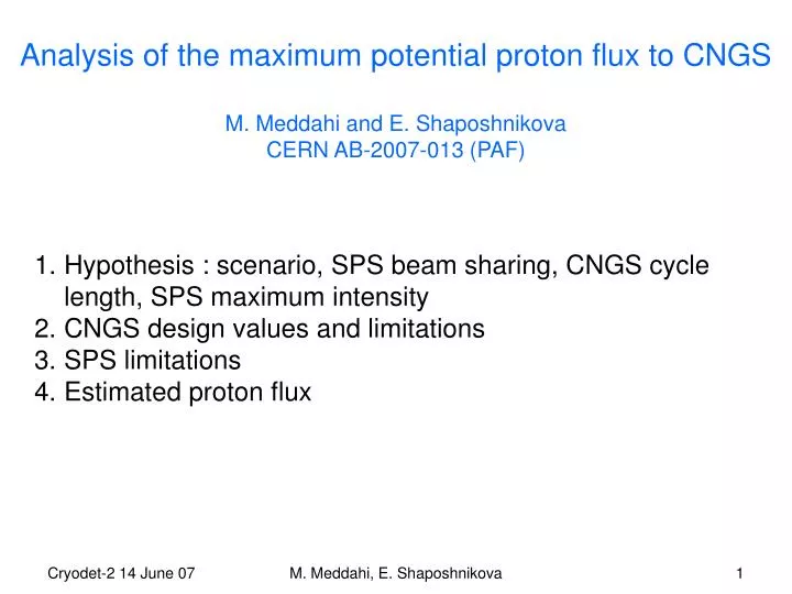
Analysis of the maximum potential proton flux to CNGS M. Meddahi and E. Shaposhnikova CERN AB-2007-013 (PAF). Hypothesis : scenario, SPS beam sharing, CNGS cycle length, SPS maximum intensity CNGS design values and limitations SPS limitations Estimated proton flux. 1.1- Scenarios.

E N D
Analysis of the maximum potential proton flux to CNGSM. Meddahi and E. ShaposhnikovaCERN AB-2007-013 (PAF) • Hypothesis : scenario, SPS beam sharing, CNGS cycle length, SPS maximum intensity • CNGS design values and limitations • SPS limitations • Estimated proton flux M. Meddahi, E. Shaposhnikova
1.1- Scenarios • Present accelerators Proton flux evaluated for 2 scenarios 2. New accelerators (SPL, PS2), “old” SPS Investigate the limitations from the CNGS facility and SPS M. Meddahi, E. Shaposhnikova
1.2- Beam sharing (S) • CNGS-FT mode: 85 % (80 %) of SPS beam time 1 FT (16.8 s) + 3 CNGS (18 s) + MD (4.8 s) => S1 = 0.45 • LHC set-up mode: 10 % of the SPS beam time pilot (7.2 s) + 2 CNGS (12 s) => S2 = 0.625 • LHC filling mode: 5 % (10 %) of the SPS beam time => S3 =0 SPS users: CNGS, LHC, FT and MD S = 0.85 x 0.45 + 0.1 x 0.625 = 0.445 (0.425) => S = 0.45 SPS users: CNGS and LHC S = 0.85 + 0.1 x 0.625 = 0.9125 (0.8625) => S = 0.85 FT: Fixed Target, MD: machine Development M. Meddahi, E. Shaposhnikova
1.3- CNGS cycle length • Present accelerators: cycle duration for the SPS-CNGS:6 s • With PS2: • Injection at energy above gamma transition: reduce losses • Injection of the PS2 beam at once: gain 1.2 s => 6 -1.2 = 4.8 s If also FT users : requirements on PS2 of a slow extraction ~ 1.2 s Different possible super cycles: 50 GeV + 50 GeV : (1.2 + 1.2) s + (1.2 + 1.2 + 1.2) s = 6 s 26 GeV + 50 GeV : (0.6 + 0.6) s + (1.2 + 1.2 + 1.2) s = 4.8 s 50 GeV + 26 GeV : (1.2 + 1.2) s + (0.6 + 1.2 + 0.6) s = 4.8 s M. Meddahi, E. Shaposhnikova
1.4- Maximum intensity in the SPS Proton flux calculation will be done for the following intensities: M. Meddahi, E. Shaposhnikova
2- CNGS design values and limitations CNGS committed to deliver 4.5x10¹⁹ pot/year for 5 years M. Meddahi, E. Shaposhnikova
2- CNGS design values and limitations (part 2) I nominal = 2.4 x 10¹³ protons per extraction I = 3.5x10¹³ per extraction, I=7x10¹³ per cycle assumed in design phase for equipment for which instantaneous intensity is important (e.g. target) I = 1.38x10²⁰ pot/year assumed (unrealistic scenario) for design of equipment for which long term effects are relevant (e.g. beam dump, cooling systems) With some exceptions -> next slide M. Meddahi, E. Shaposhnikova
Intensity limitation from the design values of the CNGS facility M. Meddahi, E. Shaposhnikova
To be noted: • After 5 years of nominal operation: • some equipments will have reached their design lifetime. • Space for any more equipments: target chamber, service gallery or surface buildings -e.g. horn capacitor banks, cooling units, extraction kicker resonant charging power supplies. • CNGS needs to run at nominal intensity for sometime to benchmark the validity of the design and the models, assess if margins exist, the reliability and performance of equipment, the beam line operation efficiency… • Activation of the equipment and tunnels – RP calculations/ studies required. Measured values during operation can be first scaled up to the new requested intensity for first estimate. M. Meddahi, E. Shaposhnikova
3.1- Main SPS limitation: RF voltage and power • Maximum available voltage in the 200 MHz system: 8 MV Example: required RF voltage for 4.8 s SPS-CNGS cycle ~ 10 MV • Maximum available SPS RF power in one 200 MHz cavity: 700 kW Example: RF power per cavity needed for SPS-CNGS cycle of 4.8 s M. Meddahi, E. Shaposhnikova
3.2- Main SPS limitation: beam losses • Critical issue for CNGS beam • Induced radiation • loss of the overall limited number of protons for the experiments • Sources: collective effects, beam sizes… Relative beam loss as a function of the SPS intensity M. Meddahi, E. Shaposhnikova
4- Estimated proton flux POT/year[1019]for 200 days of operation with 80% machine efficiency M. Meddahi, E. Shaposhnikova
Acknowledgments: M. Barnes, M. Benedikt, T. Bohl, L. Bruno, L. Ducimetiere, K. Elsener, D. Forkel-Wirth, W. Herr, R. Garoby, E. Gschwendtner,T. Linnerar, E. Montesinos, A. Pardons, S. Roesler, H. Vincke. References of the all related studies performed during the CNGS project phase can be found in CERN-AB-2007-013 (PAF). M. Meddahi, E. Shaposhnikova