Download
1 / 22
220 likes | 228 Views
This study focuses on target system specifications and options for high-power targets in neutrino factories and muon colliders. Lessons from the MERIT experiment are included. Various target concepts and materials are discussed, with an emphasis on the use of liquid mercury jets. Pion production issues are also explored, including optimization of soft pion production for low-energy pions. Proton beam and solenoid secondary containment details are examined as well.

E N D
High-Power Targets for Neutrino Factories and Muon Colliders Including Lessons from the MERIT Experiment K.T. McDonald Princeton U. MUTAC Meeting FNAL, April 6, 2009
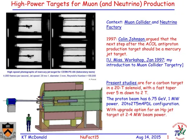
R. Palmer (BNL, 1994) proposed a solenoidal capture system. Low-energy 's collected from side of long, thin cylindrical target. Collects both signs of 's and 's, Shorter data runs (with magnetic detector). Solenoid coils can be some distance from proton beam. 4-year life against radiation damage at 4 MW. Liquid mercury jet target replaced every pulse. Proton beam readily tilted with respect to magnetic axis. Beam dump (mercury pool) out of the way of secondary 's and 's. Solenoid Target and Capture Topology Desire 1014/s from 1015p/s ( 4 MW proton beam). Highest rate + beam to date: PSI E4 with 109/s from 1016p/s at 600 MeV. Some R&D needed! Neutrino Factory Study 2 Target Concept SC-5 SC-2 SC-3 Window SC-4 SC-1 Nozzle Tube Mercury Drains Mercury Pool Proton Beam Mercury Jet Water-cooled Tungsten Shield Iron Plug Splash Mitigator Resistive Magnets ORNL/VG Mar2009
Remember the Beam Dump Target of 2 interaction lengths 1/7 of beam is passed on to the beam dump. Energy deposited in dump by primary protons is same as in target. Long distance from target to dump at a Superbeam, Beam is much less focused at the dump than at the target, Radiation damage to the dump not a critical issue (Superbeam). Short distance from target to dump at a Neutrino Factory/Muon Collider, Beam still tightly focused at the dump, Frequent changes of the beam dump, or a moving dump, or a liquid dump. A flowing liquid beam dump is the most plausible option for a Neutrino Factory, independent of the choice of target. (This is so even for a 1-MW Neutrino Factory.) The proton beam should be tilted with respect to the axis of the capture system at a Neutrino Factory, so that the beam dump does not absorb the captured ’s and ’s.
Target Options • MW energy dissipation requires liquid coolant somewhere in system • The lifetime dose against radiation damage (embrittlement, cracking, ....) by protons for most solids is about 1022/cm2. • - Target lifetime of about 5-14 days at a 4-MW Neutrino Factory • - Mitigate by frequent target changes, moving target, liquid target, ... • • Static Solid Targets • - Graphite (or carbon composite) cooled by water/gas/radiation [CNGS, NuMI, T2K] • - Tungsten or Tantalum (discs/rods/beads) cooled by water/gas [PSI, LANL] • • Moving Solid Targets • - Rotating wheels/cylinders cooled (or heated!) off to side [SLD, FNAL, SNS] • - Continuous or discrete belts/chains [King] • - Flowing powder [Densham] • • Flowing liquid in a vessel with beam windows [SNS, ESS] • - But, cavitation induced by short beam pulses cracks pipes! • • Free liquid jet [Neutrino Factory Study 2] No such thing as “solid-target-only” at this power level.
Pion Production Issues for Factory/Muon Collider, I 40MeV<KE<180MeV MARS simulations: N. Mohkov, H. Kirk, X. Ding Only pions with 40 < KE < 180 MeV are useful for later RF bunching/acceleration of their decay muons. Hg better than graphite in producing low-energy pions (graphite is better for higher energy pions as for a Superbeam). 40MeV<KE<180MeV
Pion Production Issues for Factory/Muon Collider, II • Study soft pion production as a function of 4 parameters: • Eproton • Target radius, assuming proton r = 0.3 target radius • Angle of proton beam to magnetic axis • Angle of mercury jet to magnetic axis • Production of soft pions is optimized for a Hg target at Ep ~ 6-8 GeV, according to a MARS15 simulation. [Confirmation of low-energy dropoff by FLUKA highly desirable.]
Pion Production Issues for Factory/Muon Collider, III • For Ep = 8 GeV, optimal target radius = 4 mm, • optimal proton beam angle = 80 mrad, • optimal jet-beam crossing angle = 20 mrad. • Gravity deflects a 20-m/s jet by 20 mrad in 50 cm, • Bring jet in from below proton beam for larger clearance between nozzle and beam. [Jet recrosses proton beam at z = 160 cm, y = -12 cm, i.e., close to surface of mercury pool.]
Proton Beam Solenoid Secondary Containment Syringe Pump 1 2 3 4 Jet Chamber CERN MERIT Experiment (Nov 2007) Viewports Proof-of-principle demonstration of a mercury jet target in a strong magnetic field, with proton bunches of intensity equivalent to a 4 MW beam. Pion production remains nominal for several hundred s after first proton bunch of a train. Jet disruption suppressed (but not eliminated) by high magnetic field. Region of disruption of the mercury jet is shorter than its overlap with the proton beam. Filament velocity < 100 m/s. The mercury jet showed a vertical growth to double its original height at 50 cm from the nozzle, largely independent of magnetic field.
Pump-Probe Data ? Is pion production reduced during later bunches due to disruption of the mercury jet by the earlier bunches? At 14 GeV, the CERN PS could extract several bunches during one turn (pump), and then the remaining bunches at a later time (probe). Pion production was monitored for both target-in and target-out events by a set of diamond diode detectors. These detectors showed effects of rapid depletion of the charge stored on the detector electrodes, followed by a slow RC recovery of the charge/voltage. The beam-current transformer data was used to correct for fluctuations in the number of protons per bunch. particle detectors
Beam-Current Transformer Corrections (A. Fabich) Bunch (h16) drift - offset Ringing The signal from the beam-current transformer “rang” for longer than the time between bunches. A small baseline drift occurred over a full-turn extraction. A correction to each bunch of a multibunch event was made using waveforms from single-bunch events. The integral of the corrected signal was flat between the short steps, showing the the drift and ringing have been well corrected.
Preliminary Pump-Probe Data Analysis (I. Efthymiopoulos, H. Kirk) Both target-in and target-out data showed smaller signals, relative to the pump bunches, for probe bunches delayed by 40, 350 and 700 s. Similar behavior seen in all 4 usable diamond detectors: We therefore report a corrected probe/pump ratio: The preliminary results are consistent with no loss of pion production for bunch delays of 40 and 350 s, and a 5% loss (2.5- effect) of pion production for bunches delayed by 700 s.
Optical Diagnostics of the Mercury Jet (T. Tsang) Viewport 1 30cm Viewport 2 45cm Viewport 4 90cm Viewport 3 60cm Mercury Jet Beam axis 67 milliradian Nozzle Magnet axis Viewport 2, SMD Camera 0.15 µs exposure 245x252 pixels Viewport 3, FV Camera 6 µs exposure 260x250 pixels Viewport 1, FV Camera 6 µs exposure 260x250 pixels Viewport 4, Olympus 33 µs exposure 160x140 pixels 7 T, no beam
Disruption Length Analysis (H. Park) Observe jet at viewport 3 at 500 frames/sec to measure total length of disruption of the mercury jet by the proton beam. Images of Jet Flow at Viewport 3, B = 10 T, N = 10 Tp, 2 ms/frame, Ldisruption = 17 cm.t = 6, 8, 10, 12, 14, 16, 18, 20 ms 24 GeV Disruption length never longer than region of overlap of jet with proton beam. No disruption for pulses of < 2 Tp. Disruption length smaller at higher magnetic field. Model: disruption occurs wherever the energy deposition exceeds a minimu value (that depends on B).
Filament Velocity Analysis (H. Park) Study velocity of filaments of disrupted mercury using the highest-speed camera, at viewport 2, at frame periods of 25, 100 or 500 s Shot 11019: 24-GeV, 10-Tp Beam, 10-T Field, 25µs/frame: Measure position of tip of filament in each frame, and fit for tv and v. Slope velocity tv = time at which filament is first visible
Shadow Photography Observe Projection on Vertical Plane If all filaments had the same velocity v0 and same starting time t0, but differing azimuthal angle , then observe filaments with larger start times tv and smaller velocities v. Data from shot 11019 are consistent with upwards filaments having v0 ~ 60 m/s and t0 ~ 40 s, but downwards filaments may have started later, t’0~ 70-80 s. Challenge: use projected data to extract information as to the size a of the jet in the horizontal plane.
Filament Velocities and Start Times For our projected data, take the characteristic filament velocity to be the largest velocity observed in a shot, and take the associated filament start time to be that of the largest velocity filament. Filament velocity observed to be ~ linear in number of protons, and somewhat suppressed at higher magnetic fields. Filament start time is typically much longer than 2 s = transit time of sound (pressure) wave across the jet. The start time depends on number of protons, and on magnetic field, but more study needed. 24 GeV 14 GeV 24 GeV 14 GeV
Jet Velocity Issues (with Magnet but without Beam) The velocity of surface perturbations on the jet was measured at all 4 viewports to be about 14 m/s, independent of magnetic field. The vertical height of the jet grew ~ linearly with position to ~ double its initial value of 1 cm after 60 cm, almost independent of magnetic field. Did the jet stay round, but have reduced density (a spray)?, Or did the jet deform into an elliptical cross section while remaining at nominal density?
R&D Issues for Hg Jet Target Option • Continue and extend simulations of mercury flow in and out of the nozzle. • Can we understand/mitigate the observed transverse growth of the jet out of the nozzle, which was largely independent of magnetic field. • Examine the MERIT primary containment vessel for pitting by mercury droplets ejected from the jet by the proton beam. • Extend the engineering study of a mercury loop + 20-T capture magnet, begun in Factory Study 2, in the context of the International Design Study. • Splash mitigation in the mercury beam dump, • Possible drain of mercury out upstream end of magnets. • Downstream beam window • Water-cooled tungsten-carbide shield of superconducting magnets. • High-TC fabrication of the superconducting magnets. • Hardware prototype of a continuous mercury jet with improved nozzle.
Mercury Pool Issues Both the jet and the proton beam will disrupt the mercury pool (T. Davenne) Need splash mitigation (V. Graves)
Mercury Drain, Downstream Beam Window SC-5 Window Overflow Drain Valved Drain Tungsten Shielding Mercury drain at downstream end of containment vessel is awkward – and may interfere with the pion-beam window. May be better to drain mercury between the resistive magnets and SC1.