Download
1 / 20
200 likes | 349 Views
Coupling Coil Test Facility Update. Ruben Carcagno Fermilab September 20, 2012. Introduction. About a year ago, the MICE Collaboration asked Fermilab for urgent help to provide a cold test facility for the Coupling Coils.

E N D
Coupling Coil Test Facility Update Ruben Carcagno Fermilab September 20, 2012
Introduction Ruben Carcagno | MICE Collaboration VC • About a year ago, the MICE Collaboration asked Fermilab for urgent help to provide a cold test facility for the Coupling Coils. • A plan was developed and approved by Fermilab’s directorate on January 17, 2012. Main elements of the plan: • Use a SMES cryostat from the National High Magnetic Field Lab found by LBNL • Fabricate and Install a new “Solenoid Test Facility” at Fermilab’s Central Helium Liquefier (CHL), with first use for MICE coupling coil solenoid testing • Examples of future possible use of this facility include mu2e Transport Solenoids (with test stand upgrades) and additional test stands for ITER CS modules and mu2e Production Solenoid • A Fermilab initial review of the test facility preparations took place on February 2012. The review committee agreed with the proposed approach. Work on this new facility quickly ramped up.
Test Requirements and Scope of Work Ruben Carcagno | MICE Collaboration VC • Functional Test Requirements Specified (TID-N-445) • Main objective is to train the coil and verify that it can hold a minimum test current of 210 A for at least 24 hours, and also include a thermal cycle • Statement of Work Specified (TID-N-465) • The SOW for the various institutions involved (FNAL APC/TD/AD and LBNL) has been agreed and documented • Interface Documents In Progress (TID-N-466, etc.) • Documents specifying the detailed technical interfaces between major institutional deliverables have been filled in with design information.
Cold Mass Preparations (LBNL) SC Leads Stabilization Cold QP Diodes Leads Stabilization Cooling Tubes Connections Ruben Carcagno | MICE Collaboration VC Includes cooling tubes welding, installation of leads stabilization, passive QP (cold diodes), instrumentation, etc. Installation nearly complete, leak repair in progress
Cold Mass Preparations (LBNL) Ruben Carcagno | MICE Collaboration VC • Cooling Tube Vacuum Leak found during checkout • Delivery to Fermilab delayed while leak is being fixed
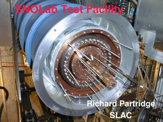
Test Cryostat Ruben Carcagno | MICE Collaboration VC The Test Cryostat was brought to Fermilab from the NHMFL in Florida and installed in the CHL building, South Annex Unnecessary internals were removed, and both the vacuum vessel and the top plate were leak checked and passed
Top Plate Insert Ruben Carcagno | MICE Collaboration VC Cryo piping more than 90% complete Current leads and coil support structure design completed, fabrication in progress
Current Leads Room Temperature 60K Intercept LTS cable to Coil lead 4.5K Intercept Ruben Carcagno | MICE Collaboration VC Conduction-cooled, optimized for 220A Two thermal intercepts: 60K (thermal strap to 4.5K GHe return pipe) and 4.5K (Wang NMR intercept to 4.5K boiling He reservoir) Low Temperature Superconductor (LTS) section between 4.5K intercept and coil leads G-10 mechanical support for magnetic forces Design and detailed drawings complete, fabrication in progress and nearly complete
Top Plate New Dished Head Ruben Carcagno | MICE Collaboration VC All valves and instruments procured, installation in progress Instrumentation tree fabricated, passed leak check Dished Head fabrication in progress at Meyer Tool, delivery September 21, 2012
Dished Head Fabrication Ruben Carcagno | MICE Collaboration VC Ready for delivery from Meyer Tool Next is Load Test and Vacuum Leak Check at Fermilab
Cryogenic System Ruben Carcagno | MICE Collaboration VC Liquid Helium and Helium gas recovery provided by the Central Helium Liquefier (unused after the Tevatron shutdown in September 2011) Up to 10 g/s of liquid helium at 4.5K will be supplied to the Coupling Coil cooling tube from a nearby CHL 10,000 Gallon liquid helium Dewar Helium inlet temperature during cooldown/warmup will be controlled to maintain a maximum cold mass gradient of 50K The return helium will be warmed up to room temperature before sending back to the CHL facility for recovery No venting to atmosphere expected during a quench (small LHe inventory in the cooling tube)
CHL Distribution System LHe Transfer Line Bayonet Can Connection to LHe Dewar Ruben Carcagno | MICE Collaboration VC Liquid Helium (LHe)Transfer Line from 10,000 Gallon LHedewar to Bayonet Can
Cryogenic System P&ID Return Gas to Warmup Heater U-Tube to Bayonet Can Ruben Carcagno | MICE Collaboration VC
Electrical and Software Systems DAQ, Quench Detection, Controls Electronic racks at CHL near cryostat Remote Test Stand control station at IB1 Magnet Test Facility Control Room Ruben Carcagno | MICE Collaboration VC Design complete, more than 25 detailed electrical drawings completed Racks assembled, networking installed and operating, checkout completed Software design complete, configuration and checkout in progress Local control station at CHL and remote station at IB1 Magnet Test Facility control E-log and measurement data will be available on the web
Local Test Stand Controls Test Stand Electronic Racks and Monitors near Test Cryostat CHL Test Stand Control Room (Climate Controlled, Acoustically Insulated) Ruben Carcagno | MICE Collaboration VC
Voltage Taps DAQ and Quench Detection System QD tripped power system when the 5.5 V threshold was exceeded after ~140ms from Quench Onset Quench developing at “End Coil 2” Quench Onset Voltage tap signals recorded during ~30 sec current decay Ruben Carcagno | MICE Collaboration VC Similar Fermilab system being used successfully for the MICE Spectrometer Solenoid Test at Wang NMR Example: Quench on 6/26/12, I = 215 A
Power System Ruben Carcagno | MICE Collaboration VC The Test Facility Power System Rack will be delivered by LBNL in September 2012 Power Supply procured by LBNL, arrived from vendor in the UK on 9/17/2012 The power system rack components are shown in the following block diagram
Safety Ruben Carcagno | MICE Collaboration VC A special ES&H safety panel has been appointed by the AD Head to review the magnetic, electrical, and mechanical safety of the test stand installation in CHL premises A permanent CHL cryogenics panel will review the cryogenics integration of the cryostat into the CHL cryogenic system A special engineering panel has been appointed by the TD Head to review the safety of the cryostat and its ancillary equipment Both AD and TD Heads will sign the Operational Readiness Clearance after all safety panels recommend safe operational readiness
Schedule Ruben Carcagno | MICE Collaboration VC • Test is expected to start in November 2012 and last for approximately two months • May be delayed because of the cold mass vacuum leak repair at LBNL
Summary Ruben Carcagno | MICE Collaboration VC A new Solenoid Test Facility at Fermilab is being constructed at the repurposed Central Helium Liquefier, with the first test stand intended for MICE Coupling Coil Solenoids testing Test Stand design is complete, fabrication and installation is near completion Delivery of the first coupling coil cold mass to be tested to Fermilab has been delayed due to a cooling tube vacuum leak repair – delivery is expected in a few weeks Testing is expected to start in (late?) November 2012 and last for approximately two months