Download
1 / 43
440 likes | 454 Views
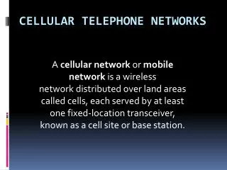
9. Telephone Networks. Basic Telephone Operation. Telephone Systems Tele means “far” and phone means “sound.” Worldwide grid of connections; point-to-point communications between many subscribers. Basic Telephone Operation. Telephone Systems Function of PBX and central office is the same

E N D
9 Telephone Networks
Basic Telephone Operation • Telephone Systems • Tele means “far” and phone means “sound.” • Worldwide grid of connections; point-to-point communications between many subscribers.
Basic Telephone Operation • Telephone Systems • Function of PBX and central office is the same • Switching one telephone line to another. • BORSCHT function for their line • Circuitry residing on line cards handles.
Basic Telephone Operation • Line Quality Considerations • Existing cable infrastructure in U.S. 50 years old.
Basic Telephone Operation • Attenuation Distortion • Local loop for telephone transmissions • Two-wire twisted-pair cable. • Transmission dependent on wire diameter, conductor spacing, dielectric constant of insulation. • Resistance of copper causes signal attenuation.
Basic Telephone Operation • Attenuation Distortion • Higher-frequency attenuation greatly curtailed by adding inductance in series with the cable. • Attenuation distortion • Difference in gain or loss at frequency with respect to reference tone 1004 Hz.
Basic Telephone Operation • Delay Distortion • Signal traveling down transmission line experiences some delay from input to output.
Basic Telephone Operation • Telephone Traffic • Intensifies between 9:00 and 11:00 in morning and 2:00 and 4:00 in afternoon.
Basic Telephone Operation • The Unit of Traffic • Trunk • Circuit or path that carries its usage for one traffic call at a time. • Traffic capacity of group of trunks • Nature or distribution of call durations or holding time.
Basic Telephone Operation • Congestion • Calls unable to reach their destination as result of excess demand for system capacity.
Basic Telephone Operation • Traffic Observation and Measurement • Continuous traffic measurement done to detect and resolve potential sources of congestion. • Traffic measurement studies determine customer calling patterns; basis for discounted toll rates.
Digital Wired Networks • Communication Links and Protocols • Simplex communication • One direction only. • Half duplex communication • Both directions but only one can talk at a time. • Full duplex • Both parties can talk at same time.
Digital Wired Networks • Communication Links and Protocols • Synchronous operation • Transmit- and receive-data clocks locked together. • Asynchronous • Clocks on transmitter and receiver not locked together.
Digital Wired Networks • Communication Links and Protocols • Protocol major functions: • Framing • Line control • Flow control • Sequence control
Digital Wired Networks • Communication Links and Protocols • Protocols • Responsible for integration of control characters within data stream and classified according to their framing technique.
Digital Wired Networks • Line Codes • Format of pulses sent over communications link. • Data first be coded or prepared for transmission. • Eliminates need for data states to be represented in terms of absolute voltage levels.
Digital Wired Networks • Line Codes • Maintaining synchronization between transmitter and receiver clocks. • Enable a form of error detection.
Digital Wired Networks • Line Codes • NRZ group of codes: encoding binary data. • See Table 9-1: NRZ Codes
Digital Wired Networks • Line Codes • RZ codes: return-to-zero line-coding formats. • See Table 9-2: RZ Codes
Digital Wired Networks • Line Codes • Biphase codes • Use in optical systems, satellite telemetry links, magnetic recording systems. • See Table 9-3: Phase-Encoded and Delay-Modulation (Miller) Codes
Digital Wired Networks • Line Codes • Multilevel binary codes • More than two levels representing the data. • See Table 9-4: Multilevel Binary Codes
Digital Wired Networks • Line Codes • Transition between logic states results in fast change in rise or fall times of transmitted pulses.
Digital Wired Networks • Line Codes • Coding scheme chosen determined by available bandwidth and need for transmitter and receiver to maintain synchronization.
The T-Carrier System and Multiplexing • Time-Division Multiplexing (TDM) • Each information signal accesses entire channel bandwidth for only small part of available time.
The T-Carrier System and Multiplexing • Time-Division Multiplexing (TDM) • Time-division multiple access (TDMA) • Transport data from multiple sources over same serial data channel. • T-carrier TDM system • PCM data from channel 1 transmitted first, then data from channel 2, and so on in sequence before process repeats.
The T-Carrier System and Multiplexing • Time-Division Multiplexing (TDM) • T1 line • Capacity for 24 individual, 64-kbps, time-division-multiplexed telephone calls. • Fractional T1 (FT1) • Only portion of T1 bandwidth being used.
The T-Carrier System and Multiplexing • Time-Division Multiplexing (TDM) • Point of presence • Point where communication carrier brings in service to a facility. • Channel service unit/data service unit (CSU/DSU). • See Table 9-7: The CSU/DSU Alarms
The T-Carrier System and Multiplexing • Time-Division Multiplexing (TDM) • Framing • Maintain synchronization of receiving equipment. • See Table 9-8: The Function of the 24 ESF Framing Bits
The T-Carrier System and Multiplexing • Time-Division Multiplexing (TDM) • Loopback capability • Causes transmitted data to be routed back to originating location.
The T-Carrier System and Multiplexing • Time-Division Multiplexing (TDM) • T1 line coding • AMI and B8ZS. • System capacity and bit rate are not unlimited.
Packet-Switched Networks • Frame Relay • Packet switching network designed to carry data traffic over public data network (PDN). • Data channels will not introduce bit errors or, at worst-case, minimal bit errors. • Committed information rate (CIR). • Committed burst information rate (CBIR).
Packet-Switched Networks • Asynchronous Transfer Mode (ATM) • Cell relay technique designed for voice, data, video traffic. • Packets or cells processed at switching centers and directed to best network for delivery. • Virtual path connection (VPC). • Virtual channel connection (VCC). • See Table 9-9: The Five ATM Service Classes
Signaling System 7 • SS7 uses physical out-of-band signaling. • ISDN and SS7 follow guidelines provided by OSI model. • Protocol analyzers • Sort through messages to identify a problem.
Troubleshooting • Digital communications troubleshooting • Recognize digital pulse distortion and identify what causes it. • Identify good pulse waveform. • Identify frequency distortion. • Describe effects of incorrect impedance on square wave. • Identify noise on digital waveform.
Troubleshooting • The Digital Waveform • Square-wave signal is digital waveform. • Effects of Noise on the Pulse • Signal’s amplitude changed by noise adding to it or subtracting from it. • Effects of Impedance on the Pulse • Square wave pulse can show effects of impedance mismatches.
Troubleshooting • Effects of Frequency on the Pulse • Digital pulses will not be distorted when passing through amplifier with sufficient bandwidth or transmission line with sufficient bandwidth. • Eye Patterns • Generated by “overlaying” on oscilloscope all digital bit signals received.