Download
1 / 15
160 likes | 173 Views
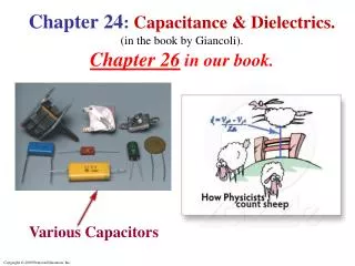
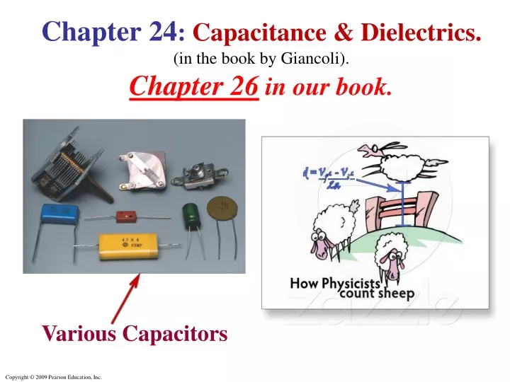
Chapter 24 : Capacitance & Dielectrics. (in the book by Giancoli ). Chapter 26 in our book. Various Capacitors. Chapter Outline. Capacitors Determination of Capacitance Capacitors in Series and Parallel Electric Energy Storage Dielectrics Molecular Description of Dielectrics.

E N D
Chapter 24:Capacitance & Dielectrics. (in the book by Giancoli).Chapter 26 in our book. Various Capacitors
Chapter Outline • Capacitors • Determination of Capacitance • Capacitors in Series and Parallel • Electric Energy Storage • Dielectrics • Molecular Description of Dielectrics
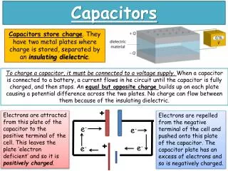
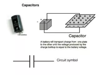
Capacitors - Definition • Capacitor Any configuration of two • conductors that are close but not touching. • A Capacitorhas the ability to store electric charge. “Parallel Plate” Capacitor
Makeup of a Capacitor • A capacitor always consists of two conductors. • These are called plates. • When the conductor is charged, the plates carry charges of equal magnitude and opposite sign. • A potential difference exists between the plates due to the charge. Section 26.1
Parallel Plate Capacitor • Each plate is connected to a terminal of the battery. • The battery is a source of potential difference. • If the capacitor is initially uncharged, the battery establishes an electric field in the wires. • This field applies a force on electrons in the wire just outside of the plates. • The force causes the electrons to move onto the negative plate. Section 26.1
Parallel Plate Capacitor, Continued • This process continues until equilibrium is achieved. • The plate, the wire & the terminal are then all at the same potential. • At this point, there is no field in the wire & the movement of the electrons ceases. • The plate is now negatively charged. • A similar process occurs at the other plate, electrons moving away from the plate & leaving it positively charged. • In its final configuration, the potential difference across the capacitor plates is the same as that between the terminals of the battery. Section 26.1
(a) A Parallel-Plate Capacitorconnected to a battery. (b)A Capacitorin a circuit diagram. Parallel Plate Capacitor Capacitorin a circuit
ExperimentShows That • When a capacitor is connected to a battery, the • charge Q on its plates is proportional to the • battery voltage V, with the proportionality • constant equal to the • Capacitance C: • This is The Definitionof capacitance. • The SI unit of capacitance is the Farad (F) • 1 F = 1 C/V
Definition of Capacitance l • As we just said, the capacitance, C, of a capacitor is the ratio of the magnitude of the charge on one plate to the potential difference between the plates. • As we also said, the SI capacitance unit is the farad (F). • The farad is a large unit, typically you will see microfarads (μF) & picofarads (pF). Capacitance • Is always a positive quantity. • Is constant for a given capacitor. • Is a measure of the capacitor’s ability to store charge • Is the amount of charge the capacitor can store per unit of potential difference.
Determination of Capacitance Parallel Plate Capacitor Earlier Result: The magnitude of the electric field E between 2 closely spaced charged plates with charge Q & area A is σ = (Q/A) surface charge density. So, E between the plates is: E = Q/(ε0A). The relation between potential difference & Eis: Integrating along a path between the plates gives the potential difference: Vba = (Qd)/(ε0A) . So, So, the capacitance of a parallel plate capacitor is: This illustrates the general procedure for calculating capacitance.
Example Calculate (a) The capacitance C of a parallel-plate capacitor whose plates are 20 cm × 3.0 cm & are separated by a 1.0-mm air gap. (b) The charge Q on each plate if a 12-V battery is connected across the two plates. (c) The electric field E between the plates. (d) An estimate of the area A of the plates needed to achieve a capacitance of C = 1 F, given the same air gap d.
Example Answers (a) The capacitance C of a parallel-plate capacitor whose plates are 20 cm × 3.0 cm & are separated by a 1.0-mm air gap. C = 53 pF (b) The charge Q on each plate if a 12-V battery is connected across the two plates. Q = CV = 6.4 10-10 C (c) The electric field E between the plates. E = V/d = 1.2 104 V/m (d)An estimate of the area A of the plates needed to achieve a capacitance of C = 1 F, given the same air gap d. A = (Cd/ε0) = 108 m2 !!!
Capacitors can now be made with capacitances of C = 1 F or more, but these are NOT parallel-plate capacitors. They are usually made from activated carbon, which acts a capacitor on a small scale. The capacitance of 0.1 g of activated carbon is about 1 F. Some computer keyboards use capacitors; depressing the key changes the capacitance, which is detected in a circuit.
Example: Cylindrical Capacitor See figure. A Cylindrical Capacitorconsists of a cylinder (or wire) of radius Rb surrounded by a coaxial cylindrical shell of inner radius Ra. Both cylinders have lengthℓ, which is assumed to be much greater than the separation of the cylinders, so “end effects” can be neglected. The capacitor is charged (by connecting it to a battery) so that one cylinder has a charge +Q (say, the inner one) and the other one a charge –Q. Derive a formula for the capacitance C.
Example: Spherical Capacitor See figure.A Spherical Capacitorconsists of two thin concentric spherical conducting shells of radius ra and rb. The inner shell carries a uniformly distributed charge Q on its surface, and the outer shell carries an equal but opposite charge –Q. Derive a formula for the capacitance C of the two shells.