Download
1 / 30
300 likes | 306 Views
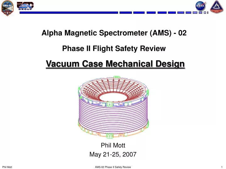
Alpha Magnetic Spectrometer (AMS) - 02 Phase II Flight Safety Review Vacuum Case Mechanical Design. Phil Mott May 21-25, 2007. Vacuum Case Overview.

E N D
Alpha Magnetic Spectrometer (AMS) - 02 Phase II Flight Safety ReviewVacuum Case Mechanical Design Phil Mott May 21-25, 2007 AMS-02 Phase II Safety Review
Vacuum Case Overview • The Vacuum Case (VC) is a structural member of the USS-02 and supports the superconducting cryogenic magnet. This is regardless of the pressure state. • Two identical Vacuum Cases are being built: • Structural Test Article (STA) • Flight • The VC weighs 1,576 lbs and is approximately 9 feet in diameter by 5 feet high. • Vacuum Case Major Components: • Upper Conical Flange • Lower Conical Flange • Upper Support Ring • Lower Support Ring • Inner Cylinder • Outer Cylinder AMS-02 Phase II Safety Review
Vacuum Case Overview (cont.) • The Vacuum Case attaches to the USS-02 at 10 locations: • 8 Interface Plate locations (4 Upper & 4 Lower) • 2 Diagonal Struts (Upper) • The superconducting cryogenic magnet is being designed and fabricated by ETH/Space Cryomagnetics Ltd. (SCL) in Culham, England. • The magnet is supported inside the VC by 16 straps attached to the Upper & Lower Support Rings. (The straps will be covered in a later presentation.) • There are 25 Feedthru Ports, not including the strap ports, that are used for Cryocoolers, Cryocooler Access Ports, Fill Ports, Vent Ports, Burst Discs, Current Leads, and cable/tube routing into and out of the Vacuum Case. • Feedthru Ports that are not used will be sealed with a blank cover plate. • All O-Ring joints are sealed with a double O-Ring configuration. • A test port is located between each O-Ring for individual leak checks AMS-02 Phase II Safety Review
Vacuum Case (Shipping Configuration) Flight Shown – STA (Flight Backup) Identical CONICAL FLANGE 2X UPPER SUPPORT RING CLEVIS PLATE 2X STRAP PORT 16X INNER CYLINDER – not installed in this configuration UPPER INTERFACE PLATE 4X OUTER CYLINDER LOWER SUPPORT RING ELECTRICAL/PLUMBING/CRYOCOOLER PORT 25X LOWER INTERFACE PLATE 4X AMS-02 Phase II Safety Review
SUPER INSULATION & VAPOR COOLED SHIELDS MAGNET RACETRACK COIL (DIPOLE COIL ROTATED 90o) SUPERFLUID HELIUM TANK VACUUM SPACE 1 x 10⁻⁶ TORR SUPER INSULATION & VAPOR COOLED SHIELDS OUTER JOINT UPPER CONICAL FLANGE UPPER SUPPORT RING INNER JOINT UPPER INTERFACE PLATE Vacuum Case Cross Section OUTER CYLINDER INNER CYLINDER LOWER INTERFACE PLATE LOWER CONICAL FLANGE LOWER SUPPORT RING AMS-02 Phase II Safety Review
Flight Vacuum Case with Magnet AMS-02 Phase II Safety Review
Vacuum Case Assembly with Misc Attachments AMS-02 Phase II Safety Review
STA Vacuum Case AMS-02 Phase II Safety Review
STA Vacuum Case with CMR installed AMS-02 Phase II Safety Review
Qualification Spin Form Al 2219-T62 Spin Forming Original plate was Al 2219-T0 2.25” thick Plate is spin formed, solution heat treated, and aged to final condition. Spin Form procedures were reviewed and approved by NASA/ES. Material tensile test samples were taken from throughout the blank. Both L and LT directions were tested. 10 locations for each direction. All test samples exceeded MIL-HDBK-5 values for Al 2219-T62 plate. Conical Flange Qualification AMS-02 Phase II Safety Review
Spin Form Blank Tests (for all production blanks) Electrical Conductivity Test per AMS 2658 8 places on both flanges Hardness Test per AMS 2658 8 places on both flanges Tensile Test per ASTM B557 L & LT directions 4 places on both flanges Conical Flange Spin Form Blanks AMS-02 Phase II Safety Review
Total spin form blanks: 7 All 7 spin form blanks were processed identical to the qualification spin formed blank. Final machined parts are dye penetrant inspected. Conical Flange AMS-02 Phase II Safety Review
Al 7050-T7451 Rolled Ring Forging. Forging Size: OD = 109.62 ID = 104.75 H = 53.25 Forging requirements and inspection data were reviewed and approved by NASA/ES. Additional tensile samples were taken from both ends of the forging for verification. Ring stiffened structure. Outer Cylinder AMS-02 Phase II Safety Review
Al 2219-T851 Rolled Ring Forging. Forging requirements and inspection data were reviewed and approved by NASA/ES. Monocoque structure. Initial machining has been completed. Inner Cylinders are left long and completed at assembly. Final machining includes machining to the proper length, with weld shrinkage allowance, and machining the weld groove. Inner Cylinder AMS-02 Phase II Safety Review
Al 7050-T7451 Rolled Ring Forging. Forging Size: OD = 110.00 ID = 97.50 H = 6.500 Forging requirements and inspection data were reviewed and approved by NASA/ES. Additional tensile samples were taken for forging verification. One Forging has been cut up and used for material tests. The Support Rings are the primary structure for the VC All 16 straps attach to the Support Rings. All Feedthru Ports are located in the Support Rings. Upper & Lower Support Rings AMS-02 Phase II Safety Review
Interface Plates / Clevis Plates • Interface Plates • Al 7050-T7451 Plate • Clevis Plates • CRES A286 AMS-02 Phase II Safety Review
Strap Port • Closeout Cap Mechanical Attachment • 8 .190-32UNJF • Double O-Ring joint • Viton, 75 Durometer • Test Port between O-Rings STRAP ASSEMBLY STRAP CLOSEOUT CAP SUPPORT RING O-RINGS (TEST PORT NOT SHOWN IN THIS VIEW) AMS-02 Phase II Safety Review
Strap Port AMS-02 Phase II Safety Review
Feedthru Ports & Cryocooler Ports • Mechanical Attachment • 8 .190-32UNJF • Double O-Ring joint • Viton, 75 Durometer • Test Port between O-Rings O-RING TEST PORT (HEX PLUG NOT SHOWN FOR CLARITY) ORIENTATION & LOCATION WILL VARY DEPENDING ON THE ATTACHED COMPONENT SUPPORT RING (UPPER OR LOWER) VACUUM CASE FEEDTHRU PORT O-RINGS MATING COMPONENT OUTER CYLINDER AMS-02 Phase II Safety Review
Feedthru Ports & Cryocooler Ports AMS-02 Phase II Safety Review
Outer Joint • Double O-Ring bolted joint. • Mechanical attachment: • Conical Flange, Upper: 232 .250-28UNJF • Outer Cylinder, Upper: 192 .250-28UNJF • Outer Cylinder, Lower: 168 .250-28UNJF & 32 .3125-24UNJF • Conical Flange, Lower: 192 .250-28UNJF • Fasteners are wet installed with Super Korpon at final assembly in England. • O-Ring material is Viton, 75 Durometer. • Test ports between each O-Ring for individual leak checks. AMS-02 Phase II Safety Review
Outer Joint INTERFACE PLATE SUPPORT RING O-RING TEST PORT CONICAL FLANGE HEX PLUG TO SEAL TEST PORT O-RING VACUUM SPACE O-RINGS TYPICAL O-RING CONFIGURATION FOR SUPPORT RING TO OUTER CYLINDER AND SUPPORT RING TO CONICAL FLANGE OUTER CYLINDER AMS-02 Phase II Safety Review
Inner Joint • Welded Joint – U Groove Design, 3 Pass. • O-Ring joint not possible due to design constraints on both sides of the joint. • Joint is designed for 3 welds – Initial plus 2 contingencies. • Weld crown will be shaved flush to accommodate ultrasonic inspection. • Three complete closeout welds will take place prior to the closeout weld on the Flight Assembly: • First Article (initial & 1 re-weld) • STA at vendor’s facility for pressure and leak tests. • STA at SCL in Culham, England. AMS-02 Phase II Safety Review
Inner Joint UPPER or LOWER CONICAL FLANGE 5/16 WELD PREP MAGNET KEEP-IN ZONE INNER CYLINDER COMPLETED WELD AMS-02 Phase II Safety Review
First Article Weld at VC Vendor AMS-02 Phase II Safety Review
STA VC Weld at Vendor AMS-02 Phase II Safety Review
STA VC Weld at SCL AMS-02 Phase II Safety Review
Closeout Weld Inspection • Joint design does not allow for x-ray inspection of the weld • Weld is visually and dye penetrant inspected. • Weld is ultrasonically inspected using a phased array system. The STA weld at the vendor was inspected manually. • Both methods have been qualified to MSFC-SPEC-504C using flat plates and the First Article. • The STA weld at the vendor required 3 minor repairs. • No repairs were required for the final STA weld in England. AMS-02 Phase II Safety Review
Vacuum Leak Tests • Both the Flight and STA VC’s were vacuum tested at the vendor. Both met the requirement of 10-6 torr. • Each O-Ring was individually tested. • Helium leak rate for both VC’s met the spec. • STA VC was leak checked again at SCL after the Cold Mass Replica was installed. AMS-02 Phase II Safety Review
Proof Pressure Tests • The STA VC has been successfully proof pressure tested with argon at the vendor and at SCL after welding. • Proof pressure: 1.8 atm absolute (26.5 psi). [1.0 x MDP] • Flight VC to be proof pressure tested after the magnet is installed and the closeout weld completed. AMS-02 Phase II Safety Review