Download
1 / 53
770 likes | 1.07k Views
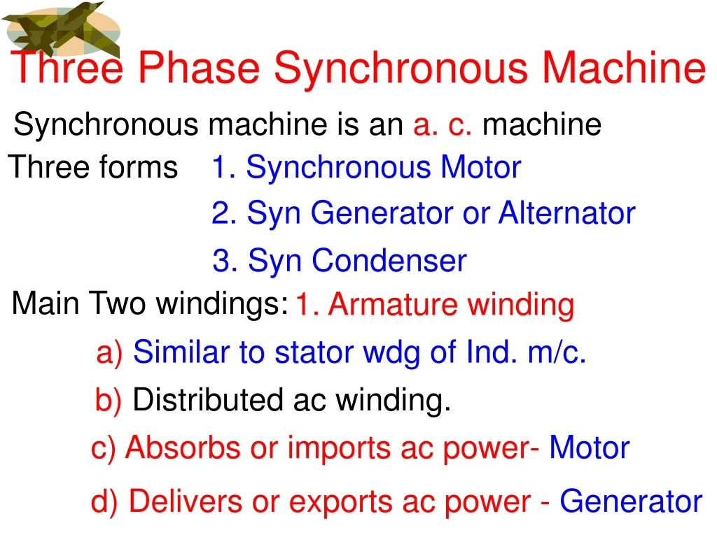
Three Phase Synchronous Machine. Synchronous machine is an a. c. machine. Three forms. 1. Synchronous Motor. 2. Syn Generator or Alternator. 3. Syn Condenser. Main Two windings:. 1. Armature winding. a) Similar to stator wdg of Ind. m/c. b) Distributed ac winding.

E N D
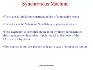
Three Phase Synchronous Machine Synchronous machine is an a. c. machine Three forms 1. Synchronous Motor 2. SynGenerator or Alternator 3.SynCondenser Main Two windings: 1. Armature winding a)Similar to stator wdg of Ind. m/c. b) Distributed ac winding. c) Absorbs or imports ac power- Motor d) Delivers or exports ac power - Generator
2. Field winding a) Similar to field wdg of dc machine b) Concentrated dc winding. c) Always absorbs or imports dc power whether Motor orGenerator Therefore, syn. m/c is a DOUBLY excited ac m/c. Armature winding is connected to ac source. Field winding is connected to dc source.
Third winding: Damper or ammortisseur winding a) Similar to compensated winding of dc machine, housed in the pole shoe. b) But short circuited similar to squirrel cage wdg c) Damps the rotor oscillations. Rotor material: Chromium-Nickel –Molybdenum steel=High tensile strength.
Construction 2. Cylindrical rotor or Round rotor or Non-salient type syn m/c 1. Salient pole or Projecting pole type syn m/c Two types: D-axis D-axis Uniform air gap Xd = Xq Xd=d-axis syn reactance Q-axis Q-axis Xq=q-axis syn reactance Salient pole Cylindrical rotor Non-uniform air gap, Xd ≠ Xq
Construction There are two types of cylindrical rotor 1. Parallel slot rotor Pole (1/3 without slot) Air gap Xd ≠ Xq Xq/Xd ≠1 Xq/Xd = 0.95 to 0.98 Parallel sided slots
Construction 2. Radial slot rotor pole Radial sided slots
Construction 2. Radial slot rotor pole Radial sided slots
Construction 1. Salient pole syn m/c 2. Cylindrical rotor syn m/c The Differences are: 1. Cylindrical rotor Salient pole
Construction 2. Non-uniform air gap Uniform air gap 3. Xd d-axis syn reactance ≠ Xqq-axis syn reactance Xd=Xq=Xs Poles ≤ 4 4. Poles > 4 5. Used in LOW speed m/c HIGH speed machine 6. Small core length, large diameter to accommodate large no of poles. Long length, small diameter to limit large centrifugal forces due to high speed.
7. Hydro-generator in which rotor is driven by Hydro-Turbine is designed with this pole. Turbo-generator in which rotor is driven by Steam-Turbine. 8. Under fault, there are more chances of deformation of rotor due to non-uniform air gap. Under fault, there are less chances of deformation of rotor due to uniform air gap. 9. Output waveform is not sinusoidal (more harmonics) Output waveform is more nearer to sine wave.
P P 10. Output Power =Electromagnetic Power + Reluctance Power =Electromagnetic Power 90 90 80 to 85
Usually field wdg is on rotor and armature wdg on stator Armature wdg R1 B2 Brushes Y2 Shaft Y1 B1 2 Slip rings Field wdg R2
Usually field wdg is on rotor and armature wdg on stator Armature wdg + – DC ON R1 B2 Brushes Y2 Shaft Y1 B1 2 Slip rings Field wdg R2 Flux is set up If rotor is rotated by Prime Mover or by Motor or by Turbine
Usually field wdg is on rotor and armature wdg on stator Generator Armature wdg + – DC ON R1 B2 Brushes Y2 Spark Shaft Y1 B1 2 Slip rings Field wdg R2 Arm Voltages t If speed is zero, no arm voltage is induced.
If DC supply is turned OFF + – DC ON R1 B2 Brushes Y2 Shaft Y1 B1 2 Slip rings R2
If DC supply is turned OFF R1 B2 Brushes Y2 Shaft Y1 B1 2 Slip rings R2 With no flux, if rotor is rotated, no arm voltage is induced.
B2 B1 Now consider armature wdg is on rotor and field wdg on stator R1 Armature wdg Y2 Y1 R2 Field wdg
B2 R1 B1 Y2 Y1 R2 DC supply is given to field wdg Flux is set up Rotate the arm By prime mover
B2 R1 B1 Y2 Y1 R2 Armature Voltage t Generator DC supply is given to field wdg Flux is set up Rotate the arm By prime mover
B2 B2 R1 B1 B1 Y2 Y1 R2 Armature Voltage t Generator DC supply is given to field wdg Flux is set up Rotate the arm by prime mover
Armature wdg R Y B N Shaft 4 Slip rings Field wdg
Armature wdg + – DC supply Given to Field R Y B N Shaft 4 Slip rings Field wdg
Now rotate the rotor Armature wdg + – DC supply Given to Field R Y B N Shaft 4 Slip rings Field wdg
Now rotate the rotor Armature wdg + – DC supply Given to Field R Y B N Shaft 4 Slip rings Field wdg t Arm Voltages
Armature wdg + – DC supply Given to Field R Y B N Shaft 4 Slip rings Field wdg t Arm Voltages No speed, arm voltage is zero.
The advantages of providing the field winding on rotor and armature winding on stator: 1. Field on rotor requires TWO slip rings. Armature on rotor requires FOUR slip rings. Less slip ring losses. 2. It is economical. For example: Rating of armature=200MVA, 11kV For this current, slip rings should be larger in size and properly insulated from the shaft for 11kV. Rating of field=1MW, 500V
Slip rings should be smaller in size and are insulated for 500V only. 3. Stationary armature can be INSULATED satisfactory for higher voltages, ie upto 33kV. 4. Stationary armature can be COOLED more efficiently upto 1000MW or above. 5. Low power field wdg gives LIGHTER rotor, so LOW torque is required to rotate the rotor . 6. Higher speed and more output are possible for a given dimensions.
N - + S Synchronous Motor Starting: If 3-phase supply is given to armature, a rotating magnetic field is produced. The speed of this rotating field is synchronous speed, Ns=120f/P. R δ The stator produces a two pole field, which is rotating in clockwise direction. If field winding is excited, poles are created on rotor as shown. Y B
N - + S Synchronous Motor Starting: If 3-phase supply is given to armature, a rotating magnetic field is produced. The speed of this rotating field is synchronous speed, Ns=120f/P. R δ The stator produces a two pole field, which is rotating in clockwise direction. If field winding is excited, poles are created on rotor as shown. N The angle between stator and rotor field axes is δ, torque angle S T=(P/ω) The torque is proportional to sinδ. Y B
N Te δ - + S Synchronous Motor Starting: The torque varies sinusoidally with time, it reverses during each half cycle. R N Therefore, the average torque over a complete cycle is ZERO. Hence, syn motor, on its own, has NO NET starting torque. S Y B
N N - - + + S S Another way: Consider the instant shown in Fig. N pole of stator repels N pole of rotor, producing anticlockwise torque. After half cycle, i. e. after 10 msec =1/2f, for 50Hz supply, stator poles occupy new positions as shown in Fig. R R N N S Te S Y B S N Y B
N N - - + + S S S pole of stator attracts N pole of rotor, producing clockwise torque. Another way: Thus rotor rotates anticlockwise at one instant and after 10msec rotor rotates clockwise direction. Due to inertia, rotor does not move in one direction and rotor remains standstill. Thus net starting torque is zero. R R Hence, synchronous motor is not self starting N S Te Te S Y B N Y B
N S Three phase supply is given to stator. Synchronously rotating magnetic field is produced. Now rotate the rotor in the same direction with same speed or speed near to syn speed. Then field wdg is excited. R Y B
N S N S Three phase supply is given to stator. Synchronously rotating magnetic field is produced. Now rotate the rotor in the same direction with same speed or speed near to syn speed. Then field wdg is excited. There is magnetic locking between stator and rotor magnetic field R With relative speed zero, stator N pole is locked with rotor S pole and stator S pole is locked with rotor N pole. Rotor will now experience a torque. If prime mover of rotor is cut off, rotor will continue to rotate in the same direction, with same syn speed. Y B
N S N S Thus rotor always rotates at synchronous speed. Hence name of this motor is synchronous motor. R If the load is applied on the rotor, rotor lags behind the stator field by some angle. Y B
N S N S Thus rotor always rotates at synchronous speed. Hence name of this motor is synchronous motor. R If the load is applied on the rotor, rotor lags behind the stator field by some angle. This angle is called as torque angle / load angle or power angle δ. The starting methods are 1. Auxiliary motor starting 2. Starting by Damper Winding (SCIM) Y B 3. SRIM starting with High Torque
BELAYTED HAPPY BIRTHDAY N H V REDDY K AKHIL DHIRAJ DESHMUKH AADITHYA VIDYASAGAR R KEERTHANA KARNAM SAGARIKA A A KHATTAB ANOUSHKA BANAVAR JANAK RAJ CHADHA E PREETHI SHOBHIT AGRAWAL YOGESH REWATKAT SAMRADNI GOMKAR NACHIKET BAPAT D V U K REDDY AJMERA RAJESH L RAHUL C RANJITH SURABHI VARMA DISHANT CHOKHANDRE PRAJAKTA MATEGADIKAR
BELAYTED HAPPY BIRTHDAY HAPPY BIRTHDAY
HAPPY BIRTHDAY MEKALANIKHITHA S VAISHNAVI V PRIYANKA T PRAVALLIKA T R S PRASANNA KUMAR SANKET THAKARE SAKSHI KAKDE M NIKHIL RAJ B S UMRE
R AC or DC Motor DC supply Y B 1. Auxiliary motor starting The auxiliary motor may be ac motor or dc motor. It is mechanically coupled with synchronous motor. The armature wdg of synchronous motor is energized from 3-phase supply. AC or DC motor is started and run near to synchronous speed
Now DC supply is given to field wdg of synchronous motor. Field poles get locked with armature poles. Synchronous motor starts running as a motor at syn speed. The auxiliary motor can now disconnected from the supply or decoupled from mechanical coupling. 2. Starting by damper winding (Squirrel cage Induction motor starting)
2. Starting by damper winding Pole Damper Bars (skewed) (Squirrel cage Induction motor starting) In order to make the motor self starting, the damper or amortisseur wdg is embedded in slots in the rotor pole faces. This wdg is short –circuited at both ends by end rings. This damper winding is similar to squirrel cage wdg of 3-ph induction motor. Damper Bars End Ring
2. Starting by damper winding (Squirrel cage Induction motor starting) In this case, the syn motor can be started by star-delta starting, reactor starting or auto-transformer starting. When 3-phase supply is given to armature, a rotating magnetic field is established. Damper wdg develop induction motor torque. The rotor is accelerated and speed is near to synchronous speed. Before starting the field wdg can be short-circuited with or without some resistance With some resistance, starting torque will be more. Now the field wdg is open circuited and is energized from a DC source, stator and rotor poles will lock together. Then rotor will run at synchronous speed.
+ R ¯ Y B 3. Slip Ring Induction Motor starting with High Starting Torque (Synchronous – Induction Motor) First it is operated as SRIM and then synchronous motor, therefore, syn motor may be called as Syn-duction motor.
For load requiring high starting torques, this type of starting method is used. Rotor is similar to SRIM or wound rotor induction motor. At the time of starting high resistance is inserted in rotor circuit to develop high starting torque. As speed increase, this resistance is gradually reduced to zero . The rotor short circuit is removed and rotor wdg is switched over to DC supply. Thus rotor poles are created and are attracted by stator poles and synchronism is achieved.
Excitation Systems Field winding Always absorbs or imports dc power whether Motor orGenerator operation. Field winding is connected to dc source. The excitation systems are: 1. DC exciter
1. DC Exciter Alternator Field Field of Pilot Exciter Field of main Exciter AlternatorOutput Shaft Stator Rotor Stator Rotor Rotor 3-Phase Alternator Pilot Exciter Main Exciter Alternator field on rotor is connected to armature of main exciter on rotor through slip rings and brushes.
1. DC Exciter An old conventional method of exciting field winding. Three machines 1. Pilot exciter: DC shunt generator feeding field wdg of main exciter 2. Main exciter: Separately Excited DC generator feeding field wdg of main alternator. 3. Main 3-phase alternator: They are mechanically coupled and driven by same shaft.
2. Static Excitation Battery Bank Brushes Slip rings Thyrister Rectifier TR
2. Static Excitation No rotating type of exciter, no friction. Initially field winding is excited by battery bank through slip rings and brushes. After building up of voltage, the output voltage is fed back to field through transformer and rectifier. Then battery bank is disconnected. Use of reliable and high power SCR ( silicon controlled rectifier) gives fast response. If other generators are in operation, then there is no need of battery bank for new generator.