Download
1 / 19
190 likes | 192 Views
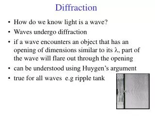
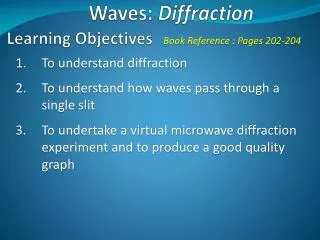
PHY 102: Waves & Quanta Topic 8 Diffraction II John Cockburn (j.cockburn@... Room E15). Single slit Intensity distribution Double slit intensity distribution Resolving powers X-ray diffraction. Single Slit Diffraction.

E N D
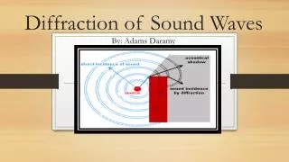
PHY 102: Waves & Quanta Topic 8 Diffraction II John Cockburn (j.cockburn@... Room E15)
Single slit Intensity distribution • Double slit intensity distribution • Resolving powers • X-ray diffraction
Single Slit Diffraction • From diagram, can see that for slit of width A, we will get destructive interference (dark band on screen) at angles which satisfy…..: Choice of a/2 and a/4 in diagram is entirely arbitrary, so in general we have a dark band whenever; (m=±1, ±2, ±3………..)
Position of dark fringes in single-slit diffraction If, like the 2-slit treatment we assume small angles, sin ≈ tan =ymin/R, then Positions of intensity MINIMA of diffraction pattern on screen, measured from central position. Very similar to expression derived for 2-slit experiment: But remember, in this case ym are positions of MAXIMA In interference pattern
Intensity distribution Width of central maximum • We can define the width of the central maximum to be the distance between the m = +1 minimum and the m=-1 minimum: Ie, the narrower the slit, the more the diffraction pattern “spreads out” image of diffraction pattern
Single-slit diffraction: intensity distribution To calculate this, we treat the slit as a continuous array of infinitesimal sources: Can be done algebraically, but more nicely with phasors………………..
Single-slit diffraction: intensity distribution E0 is E-field amplitude at central maximum = total phase difference for “wavelets” from top and bottom of slit
Single-slit diffraction: intensity distribution How is related to our slit/screen setup? Path difference between light rays from top and bottom of slit is From earlier (2-slit)
“real” intensity distribution for double slits The distribution derived earlier is for the idealised case of infinitely narrow slits:
“real” intensity distribution for double slits If we allow the slits (spacing d) to have finite width a, then the TOTAL Intensity distribution is the product of the 2-slit intensity distribution and the intensity distribution for a single slit of width a:
“real” intensity distribution for double slits “ideal” pattern Single slit pattern “real” pattern
Missing Orders Positions of maximum intensity In interference pattern Positions of zero intensity In diffraction pattern So when: Every nth order is missing in the 2-slit intensity distribution…….
Example Calculation • An interference pattern is produced by 2 identical parallel slits of width a and separation (between centres) d = 3a. Which interference maxima will be missing in the observed pattern?
Circular apertures and resolving powers Diffraction effects can, of course be observed with any shape of aperture (see 2nd year optics course). Take circular aperture, for example: Angular radius of bright central spot (Airy disc):
Rayleigh Criterion • Two point objects can just be resolved when the first minimum in the • diffraction pattern from one overlaps with the centre of the Airy disc • (central bright spot) in the diffraction pattern of the other. ie limiting angle of resolution given by: increase resolution by going to shorter wavelengths (eg electron microscopes)
X-ray diffraction X-rays: electromagnetic radiation with wavelengths ~10-10m……….. Expect to see interference/diffraction effects when interacting with objects on this length scale……… Atomic spacing in crystals/complex molecules ~ 10-10m…….X- ray crystallography
X-ray diffraction Angle of incidence = Angle of scattering Constructive interference from adjacent planes of atoms, spacing d: “Bragg condition” (NB factor of 2)