Download
1 / 21
210 likes | 294 Views
Main Injector Upgrades. Ioanis Kourbanis March 15 , 2005. Decay Pipe. MI in 2005. ’s to Soudan. NuMI extraction line. Outline. Introduction Power Supplies RF systems Large Aperture Quads Gammat-Jump Collimators. Introduction.

E N D
Main Injector Upgrades Ioanis Kourbanis March 15 , 2005
Decay Pipe MI in 2005 ’s to Soudan NuMI extraction line Kourbanis-Proton Driver Director's Review
Outline • Introduction • Power Supplies • RF systems • Large Aperture Quads • Gammat-Jump • Collimators Kourbanis-Proton Driver Director's Review
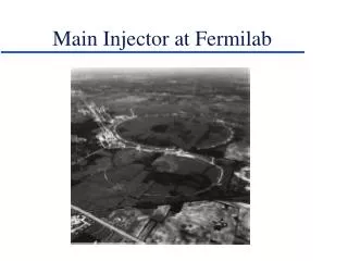
Introduction • Main Injector is currently delivering beam to the pbar target and to NuMI on the same cycle with a 0.5 Hz rep rate. • The total MI beam intensity can be as high as 3.5E13p/cycle and is expected to increase to about 5.5-6E13p/cycle with the implementation of beam stacking for NuMI. • For the Proton Driver MI is expected to deliver up to 1.5E14p/cycle with 0.67 Hz rep. rate. Kourbanis-Proton Driver Director's Review
Power Supplies • At present the max. accelerating rate is 205GeV/sec. • The power supplies can support a max accelerating rate of 280 GeV/sec. With this the MI cycle time can be reduced to 1.5 sec (assuming a Linac as Injector). • To reduce the MI cycle time further down to 1 sec the max. accelerating rate has to increase to 325GeV/sec. • We will need some power supply upgrades to achieve this accelerating rate. Kourbanis-Proton Driver Director's Review
Present Power Supply Capability Minimum Cycle Ramp 1.75sec Present MI Ramp 1.87sec Time for Sync. Injection Kourbanis-Proton Driver Director's Review
Picture of Current MI Ramp MI Bend Current MI Bend Voltage Sync. Injection Time Time (sec) Kourbanis-Proton Driver Director's Review
MI 1 Sec Ramp with Linac Injection Kourbanis-Proton Driver Director's Review
MI Power Supplies Mod. For 1 Sec Ramp • Upgrade four more Quad Supplies to higher voltage (1200Vdc) • Add three more Bend Supplies. • Add one more 345kV Transformer and Harmonic Filters. • Total cost is estimated to be around $6M. Kourbanis-Proton Driver Director's Review
MI RF System • The existing MI rf system does not have enough voltage or power to accelerate the beam intensity required. • We can increase the rf power available by adding another power tube to each cavity. The cavities have an extra port available. See John Reid’s talk. • We can add more cavities to increase the rf voltage needed for faster ramps (we have 3 spare cavities). • A design for a new rf system has been developed. See Dave Wildman’s talk. Kourbanis-Proton Driver Director's Review
MI Cavity Kourbanis-Proton Driver Director's Review
MI RF Power Calculation (18 Cavities) • Cavity Q=4700 (at max ramp rate), R=4.9E5Ω, V(gap)=240KV • 18 Cavities, each delivering 350KW for a total of 6.3MW • Min bucket area 1.24eV-sec(280 Gev/sec), 0.66eV-sec (325 GeV/sec) Kourbanis-Proton Driver Director's Review
MI RF Power Calculations (20 Cavities) • Cavity Q=4700 (at max ramp rate), R=4.9E5Ω, V(gap)=240KV • 20 Cavities, each delivering 350KW for a total of 7.0MW • Min bucket area 1.77eV-sec(280 Gev/sec), 1.13eV-sec (325 GeV/sec) Kourbanis-Proton Driver Director's Review
Wide Aperture Quads (WQB) • In all of the MI extraction areas the quadrupoles upstream of the Lambertson magnets limit the physical aperture leading to beam loss. • We plan to replace these quadrupoles with larger aperture ones (4in instead of 3.3in). • The first of these quadrupoles will ready for magnetic testing in early May. • We expect to have 4-7 of the WQB magnets ready for installation during this year’s shutdown. Kourbanis-Proton Driver Director's Review
Beam Profiles with the old and WQB quads Old Lambertson Location Proposed Lambertson Location Kourbanis-Proton Driver Director's Review
WQB Cross Sections Kourbanis-Proton Driver Director's Review
WQB Laminations Kourbanis-Proton Driver Director's Review
Coils of the first WQB magnet Kourbanis-Proton Driver Director's Review
Gamma-t jump system • A gamma-t jump system is needed in MI to reduce the longitudinal emittance growth during transition crossing and prevent beam loss. • We have a conceptual design of a first order gamma-t system consisting of 8 sets of pulsed quadrupole triplets. It provides a Δγτfrom 1 to -1 within 0.5 ms. • The only big issue is to find the free space for the component installation. Kourbanis-Proton Driver Director's Review
MI Collimation System • The combination of a very high amount of beam power injected into the MI (~0.13 MW), tight MI aperture defined by the extraction and injection Lambertsons, imposes serious constraints on beam losses. • An MI collimation system that gets rid of beam not captured during slip stacking will be needed in the immediate future. Kourbanis-Proton Driver Director's Review
CONCLUSIONS • A series of upgrades is required for MI to run at Proton Driver Intensities and rep rates. • Most of the technical issues have been understood. • The large aperture quads and the MI collimation system will be in place before the Proton Driver since they are needed for the current MI operation. • An rf R&D program should start ASAP. Kourbanis-Proton Driver Director's Review