Download
1 / 58
680 likes | 1.09k Views
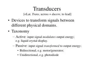
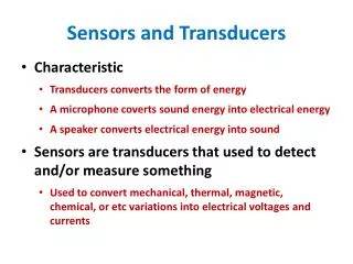
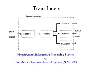
2 Sensors and transducers 2.1 Sensors and transducers Sensor is an element which produces a signal relating to the quantity being measured. (传感器) Transducers are elements that when subject to some physical change experience a related change. (变送器) Sensors are transducers.

E N D
2 Sensors and transducers 2.1 Sensors and transducers Sensor is an element which produces a signal relating to the quantity being measured.(传感器) Transducers are elements that when subject to some physical change experience a related change.(变送器) Sensors are transducers.
2.2 Performance terminology Range The range of a transducer is the limits between which the input can vary. Error Error is the difference between the result of the measurement and the true value of the quantity being measured. Error=measured value-true value Accuracy Accuracy is the extent to which the value indicated by a measurement system might be wrong. (percentage of full range output or full-scale deflection) Sensibility The sensibility is the relationship indicating how much output you get per unit input.
Hysteresis error The hysteresis error is the maximum difference in output for increasing and decreasing values. Non-linearity error Theerror occurs as a results of the assumption that the transducer has a linear relationship between the input and output. (Percentage of the full range output)
Repeatability The repeatability is the ability of the transducer to give the same output for repeated applications of the same input value. (Percentage of the full range output) Reproducibility The reproducibility of a transducer is its ability to give the same output when used to measure a constant input and is measured on a number of occasions. (Percentage of the full range output) Stability The stability of a transducer is its ability to give the same output when used to measure a constant input over a period of time.(The term drift is often used to describe the change in output that occurs over time.) Dead band(Dead space) The dead band of a transducer is the range of input values for which there is no output.
2.2.1 Static and dynamic characteristics Static characteristics are the values given when steady-state condition occur, i.e. the values given when the transducer has settled down after having received some input. (The terminology defined above refers to such a state) Dynamic characteristics refer to the behavior between the time that the input value changes and the time that the value given by the transducer settles down to the steady-state value.
Response time (output corresponding to the value of input , 95%) Time constant is the 63.2% response time. Rise time is the time taken for the output to rise to some specified percentage of the steady-state output.(from 10% to 95% of output) Settling time is the time taken for the output to settle to within some percentage, e.g. 2%, of the steady-state value.
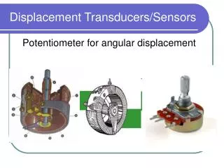
2.3 Example of sensors and selection 2.3.1 Displacement Potentiometer V0/Vs=R23/R13 Consider the effect of the a load RL , there is Error=xVs –VL=VsRP(x2-x3)/RL
Capacitive element Capacitance Permittivity of the dielectric Permittivity of free space Area of overlap Plate separation
2.3.2 Velocity Incremental encoders Tachogenerator
2.3.3 Force Strain gauge load cell
2.3.4 Fluid pressure 2.3.5 Liquid flow 2.3.6 Liquid level 2.3.7 Temperature
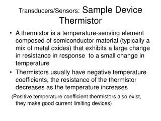
2.3.7 Temperature Bimetallic strips Resistance temperature detectors (RTDs)
Law of intermediate temperature, For example, a type E thermocouple, the following is data from standard tables. Temp.(oC) 0 20 200 e.m.f(mV) 0 1.192 13.419 What will be the thermoelectric e.m.f with a cold junction at 20oC?
2.3.8 Proximity Microswitch, Magnetic reed switch, Inductive proximity switch, Eddy current proximity switch, Photoelectric proximity switches. 2.4 Selection of sensors 1 Identify the nature of the measurement required. 2 Identify the nature of the output required from the sensor. 3 Identify possible sensors. Homework: page 40, problems 4,5,8,13
2.4 Signal conditioning 2.4.1 Interfacing Interface is the term used for the item that is used to make connections between devices, and/or between devices and ports. The interface often contains signal conditioning and protection. 2.4.2 Signal-conditioning processes 1 There are protections to prevent damage to the next element as a result of high current or voltage. 2 Getting the signal into the right type of signal. 3 Getting the level of the signal right. 4 Eliminating or reducing noise. 5 Signal manipulation.
2.5 Digital signal and filtering The term filtering is used to describe the process of removing a certain band of frequencies from a signal and permitting others to be transmitted.
Pass band. Stop band. Cut-off frequency (boundary between stopping and passing) Passive filter made up using only resistors, capacitors and inductors. Active filter is the filter which also involves an operational amplifier. Low-pass filters are very commonly used as part of signal conditioning. The cut-off frequency of low-pass filter is generally selected as 40Hz.
Digital signal Analogue-to-digital conversion unit composes of a sample and hold unit and an analogue to digital converter. The resolution of an analogue-to-digital converter with the word length of n is
Successive approximations method is the most commonly used method. This involves selecting the most significant bit that is less than the analogue value, then adding successive lesser bits for which the total does not exceed the analogue value. The conversion time is .